Vertical heating installation device for coupler

A technology for installation devices and couplings, which is applied in the direction of lifting devices, metal processing, metal processing equipment, etc., can solve the problems of low installation efficiency, threats to the safety of peripheral equipment and operators, and difficult installation, so as to achieve high installation efficiency, Avoid contact with high-temperature parts and facilitate operation

Pending Publication Date: 2021-03-09
SHANDONG IRON & STEEL CO LTD
View PDF0 Cites 0 Cited by
  • Summary
  • Abstract
  • Description
  • Claims
  • Application Information

AI Technical Summary

Problems solved by technology

[0005] The purpose of the present invention is to provide a vertical heating installation device for shaft couplings to overcome the problems in the

Method used


Image

  • Vertical heating installation device for coupler
  • Vertical heating installation device for coupler
  • Vertical heating installation device for coupler

Examples


Example Embodiment

[0062] The technical solutions in the embodiments of the present invention will be described below, and the described embodiments are merely, and embodiments are merely the embodiments of the present invention, not all of the embodiments. Based on the embodiments in the present invention, all other embodiments obtained by those of ordinary skill in the art are in the range of the invention.

[0063] The present invention will be described in detail below with reference to the drawings. It should be noted that the features in the present invention in the present invention can be combined with each other in the case of an unable conflict.

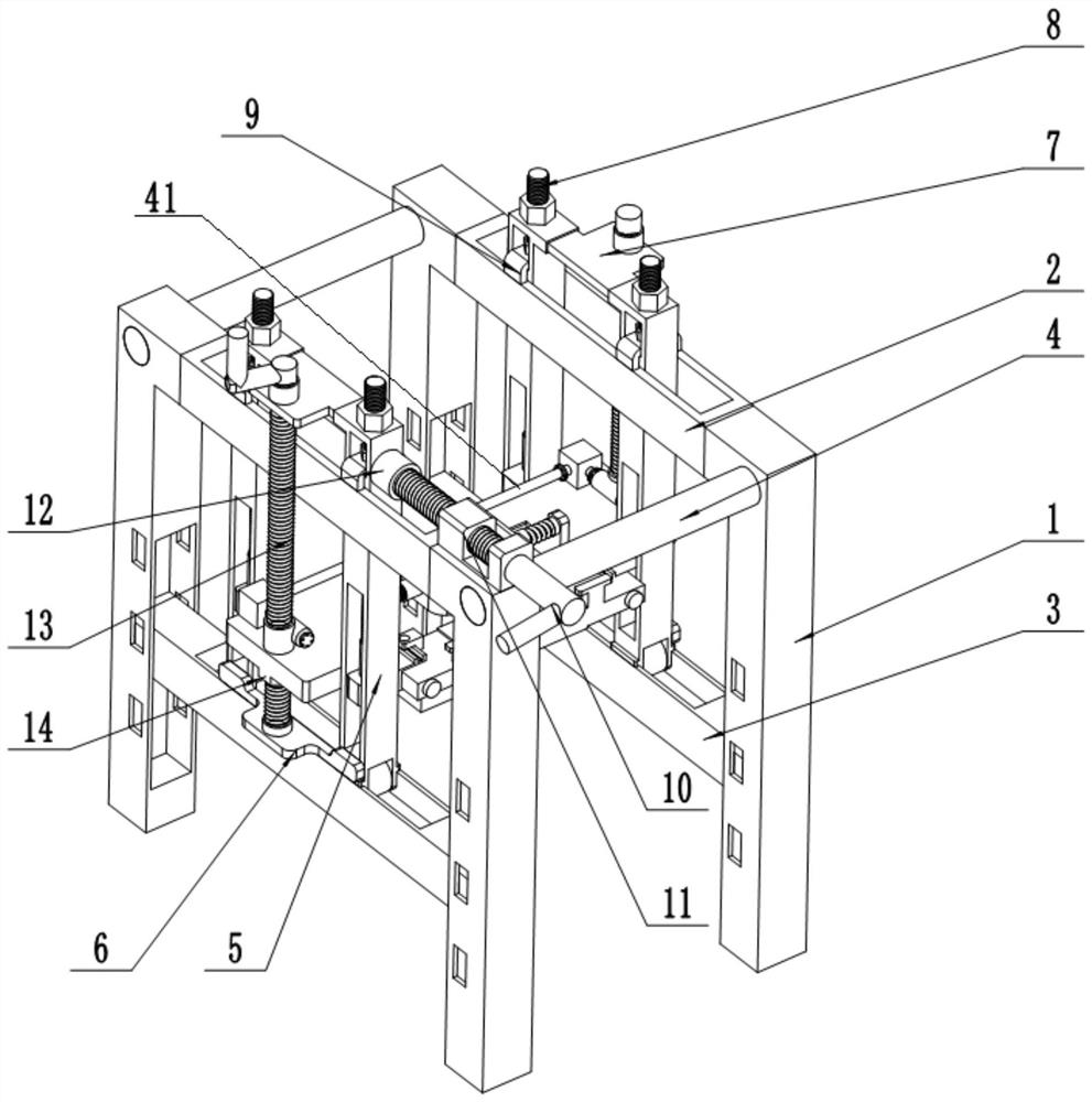
[0064] The "transverse" in the present invention is the same as the extension direction of the transverse driving rod 10, and "longitudinal" is the same as the extension direction of the drive shaft 41, and the "upper and lower" direction is the same as the extending direction of the column 1.

[0065] Specific embodiment of the coupling of the p...


PUM


Abstract

The invention provides a vertical heating installation device for a coupler. The vertical heating installation device comprises a first part and a second part, wherein the first part and the second part are oppositely arranged; and each of the first part and the second part comprises a fixed frame, a transverse moving frame, a lifting table, a lifting drive structure and a longitudinal pushing mechanism. The installation device further comprises a connecting rod, a fixed clamping plate, a movable clamping plate and a locking device. According to the vertical heating installation device for thecoupler, the coupler can be clamped and fixed through a mechanical structure, and the vertical heating installation device is more reliable compared with manual work; and in addition, when manual operation is not convenient after the coupler is heated, the problem of difficult operation is solved.

Description

technical field [0001] The invention belongs to the technical field of shaft coupling installation, and in particular relates to a vertical heating installation device for shaft couplings. Background technique [0002] In the field of mechanical equipment manufacturing, couplings are widely used in equipment connection as a relatively common connection. The coupling includes two butt flanges. In the process of connecting two shafts, each butt flange is fixedly connected to the corresponding shaft, and the two butt flanges are fixedly connected by bolt components, and finally realizes mutual fixation of the two axes. [0003] First of all, the design size of mechanical equipment is getting larger and larger, and the size and weight of couplings are also increasing. During equipment installation and maintenance, manual installation of couplings is becoming more and more difficult. In addition, if the installation process If the coupling falls, it is easy to cause injury to t...

Claims


Application Information

Patent Timeline
IPC IPC(8): B66F7/00B66F7/28B23P11/02
CPCB23P11/025B66F7/025B66F7/28
Inventor 李雪涛李发宏赵峥李山峰孙波林雅琴李绪东孔峰
Owner SHANDONG IRON & STEEL CO LTD
Why Eureka
Try Eureka