
Micro-channel evaporator

An evaporator and micro-channel technology, applied in evaporators/condensers, household appliances, refrigeration components, etc., can solve the problems of large evaporators, low heat exchange efficiency, and occupying the volume of refrigerators, etc., to increase heat exchange area, Improve heat transfer efficiency and facilitate processing

Pending Publication Date: 2021-03-09
CHANGZHOU CHANGZHENG HEAT EXCHANGER TECH
View PDF0 Cites 0 Cited by
  • Summary
  • Abstract
  • Description
  • Claims
  • Application Information

AI Technical Summary

Problems solved by technology

The evaporator is designed in the refrigerating room of the refrigerator. The evaporator is an expansion tube structure with low heat transfer efficiency. The evaporator is large in size and occupies the internal volume of the refrigerator.

Method used


Image

  • Micro-channel evaporator
  • Micro-channel evaporator
  • Micro-channel evaporator

Examples


Embodiment Construction

[0034] The present invention will be further described below in conjunction with the accompanying drawings.

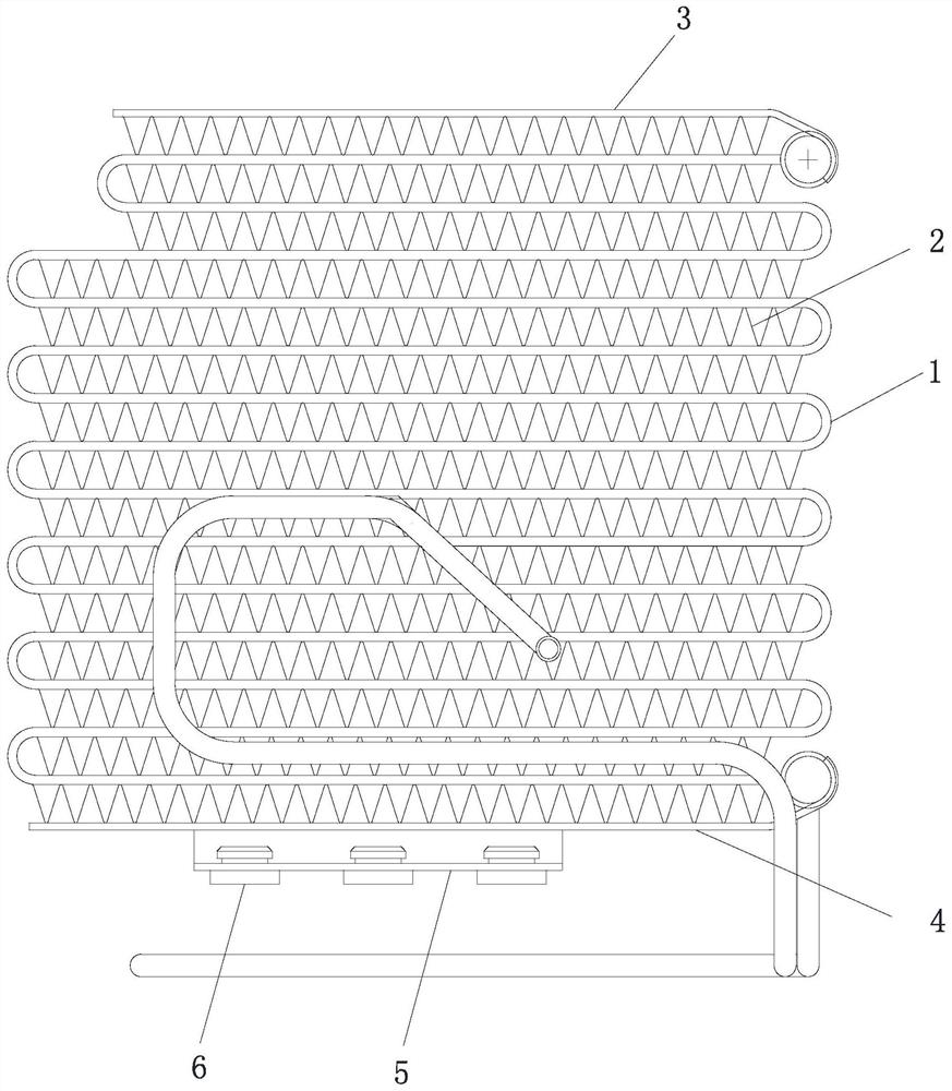
[0035] Such as Figure 1 to Figure 8 A microchannel evaporator shown includes a flat tube 1, fins 2, a top plate 3, a bottom plate 4 and a mounting plate 5, the flat tube 1 is bent into an S-shape, and the fins 2 are arranged on the S-shaped flat In the gap of the tube 1; the top plate 3 and the bottom plate 4 are respectively arranged on the opposite sides of the flat tube 1, such as the upper and lower sides, the top plate 3 and the bottom plate 4 are all parallel to the axial direction of the flat tube 1, and the distance between the top plate 3 and the flat tube 1 The space, the bottom plate 4 and the flat tube 1 are all connected by fins 2. In this embodiment, the fins 2 and the flat tube 1, top plate 3 and bottom plate 4 are fixedly connected by adhesive; the mounting plate 5 is connected to the bottom 3 by screws. The mounting plate 5 is provided with a positio...


PUM


Abstract

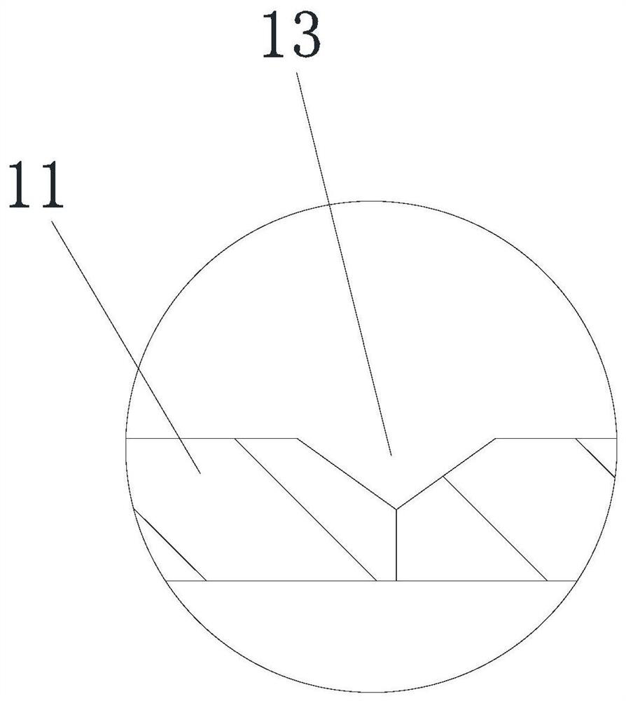
The invention relates to a micro-channel evaporator. The micro-channel evaporator comprises a flat tube and a fin, wherein the flat tube is bent to be S-shaped; the fin is arranged in a gap of the S-shaped flat tube; the flat tube comprises one outer wall plate and a plurality of inner guide tubes; the inner guide tubes are arranged abreast; the outer wall plate are bent along the outer walls of the inner guide tubes so as to cover the inner guide tubes, and the two ends of the outer wall plate are fixedly connected; the fin comprises a plurality of main body parts and a plurality of bending parts, and the main body parts and the bending parts are mutually connected to form a wave-shaped structure; a plurality of windows are arranged on the main body parts, two budged plates are arranged on each window and are symmetrically arranged on the two opposite faces of each of the main body parts, and the height difference exists between the each bulged plate and the surface of the each main body part. The micro-channel evaporator is small in size and is high in heat exchange efficiency.

Description

technical field [0001] The invention relates to the technical field of heat exchangers, in particular to a microchannel evaporator. Background technique [0002] At present, for air-cooled refrigerators, the larger the internal volume of the general refrigerator, the higher the price. The evaporator is designed in the refrigerating room of the refrigerator. The evaporator is an expansion tube structure with low heat transfer efficiency. The evaporator is large in size and occupies the internal volume of the refrigerator. In order to increase the internal volume of the refrigerator, the evaporator needs to be small in size and high in heat exchange efficiency. Contents of the invention [0003] The technical problem to be solved by the present invention is to provide a micro-channel evaporator with small volume and high heat exchange efficiency aiming at the above defects. [0004] The technical solution adopted by the present invention to solve its technical problems is ...

Claims


Application Information

Patent Timeline
Patent Type & Authority Applications(China)
IPC IPC(8): F25B39/02F25D23/00
CPCF25B39/02F25D23/006
Inventor 陈建元郑磊
Owner CHANGZHOU CHANGZHENG HEAT EXCHANGER TECH
Learn More