
Wheel type range finder

A wheel-type rangefinder and distance-measuring wheel technology, which is applied in the field of rangefinders, can solve the problems of inconvenient measurement, large measurement error, fixed and rigid overall structure, etc., and achieve the effect of improving accuracy and convenient observation

Pending Publication Date: 2021-03-09
瑞扬电力有限公司
View PDF14 Cites 7 Cited by
  • Summary
  • Abstract
  • Description
  • Claims
  • Application Information

AI Technical Summary

Problems solved by technology

[0003] A wheeled distance meter generally includes a distance measuring wheel, a push rod and a counting device. The operator pushes the push rod to move the distance measuring wheel, and the distance is calculated by the number of laps the distance measuring wheel travels. The structure is relatively fixed and rigid, and the distance-measuring wheel tends to go backwards under the influence of factors when walking, resulting in inaccurate counting of the counting device. The existing wheel-type distance meter is only equipped with a walking distance-measuring wheel. It is easy for the distance measuring wheel to fall, which leads to low measurement efficiency and large measurement error. The counting device of the existing wheel range finder is generally installed near the distance measuring wheel, and it is necessary to be close to the counting device to observe when reading. It is very laborious, and the existing wheeled distance meter is not convenient for measuring the track. During the measurement, the distance measuring wheel will easily slip off the track. Therefore, we propose a wheeled distance meter

Method used


Image

  • Wheel type range finder
  • Wheel type range finder
  • Wheel type range finder

Examples


Embodiment Construction

[0026] The following will clearly and completely describe the technical solutions in the embodiments of the present invention with reference to the accompanying drawings in the embodiments of the present invention. Obviously, the described embodiments are only some, not all, embodiments of the present invention. Based on the embodiments of the present invention, all other embodiments obtained by persons of ordinary skill in the art without making creative efforts belong to the protection scope of the present invention.

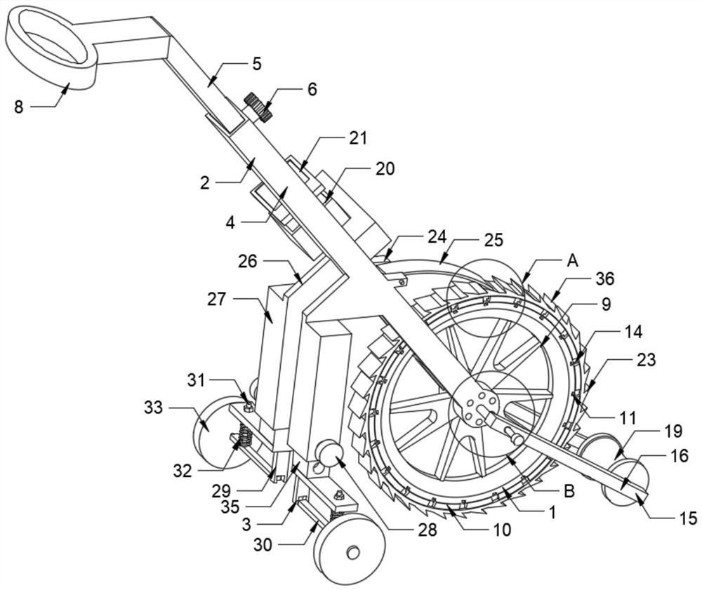
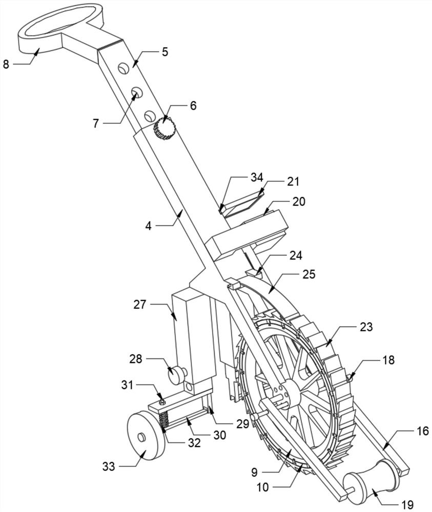
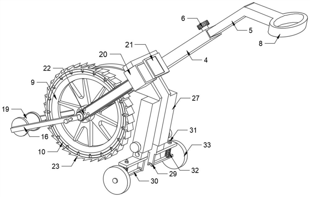
[0027] see figure 1 , figure 2 and image 3 , the present invention provides a technical solution: a wheel-type rangefinder, including a distance-measuring wheel 1 and a handle 2, the outside of the distance-measuring wheel 1 is provided with a handle 2, and also includes: an auxiliary support mechanism 3, a track positioning mechanism 15 and an anti-backward mechanism 36, the lower end of the handle 2 is provided with an auxiliary support mechanism 3, and ...


PUM


Abstract

The invention discloses a wheel type range finder which comprises a range finding wheel and a handle arranged outside the range finding wheel. The wheel type range finder further comprises an auxiliary supporting mechanism, a track positioning mechanism and an anti-backward-walking mechanism. The auxiliary supporting mechanism is arranged at the lower end of the handle, and the track positioning mechanism is arranged at the end, located outside the range finding wheel, of the handle. The anti-backward-walking mechanism is arranged on the outer side of the range finding wheel. The handle comprises a supporting rod and an adjusting rod. According to the wheel type range finder, a clamping groove is formed in the top of the supporting rod, a clamping rod on a mounting plate is clamped in theclamping groove of the supporting rod, and the mounting plate can be conveniently disassembled and assembled. When the wheel type range finder is used, due to the fact that the distance between the display screen of a counter and an operator is large, the operator cannot see the numbers on the display screen clearly and thus cannot know the walking mileage in time. The numbers displayed on the display screen can be amplified through a magnifying glass on the mounting plate, so that an operator can see the numbers more clearly, the walking mileage can be known in time, and the observation is more convenient.

Description

technical field [0001] The invention relates to the technical field of rangefinders, in particular to a wheeled rangefinder. Background technique [0002] The wheel rangefinder is a kind of distance measuring device, which is mainly designed and manufactured for outdoor distance measurement, and is suitable for various ground conditions, including grassland, construction sites with rough hillsides, etc. The wheel distance meter has a long measurement distance and the digital display system is clear and accurate, so it is widely used in the measurement and evaluation of road engineering, pipeline laying engineering, professional surveying and mapping, etc. Construction measurement, and measurement of farmland construction management, etc., its time-saving and convenient advantages have been discovered and utilized by more and more people. question. [0003] A wheeled distance meter generally includes a distance measuring wheel, a push rod and a counting device. The operator...

Claims


Application Information

Patent Timeline
Patent Type & Authority Applications(China)
IPC IPC(8): G01B5/02G01C22/00
CPCG01B5/02G01C22/00
Inventor 严浩夏小龙董继军
Owner 瑞扬电力有限公司
Learn More