
Ground surface change detection equipment based on remote sensing image processing

A technology for remote sensing image processing and change detection, which is applied to camera devices, etc., can solve the problems of difficult monitoring work, poor monitoring effect, remote geographical location, etc., and achieve the effect of improving coverage, improving detection effect, and reducing monitoring cost.

Inactive Publication Date: 2021-03-09
马新国
View PDF0 Cites 2 Cited by
  • Summary
  • Abstract
  • Description
  • Claims
  • Application Information

AI Technical Summary

Problems solved by technology

[0004] However, the location of the landslide disaster is often in a bad environment, remote geographical location, sparsely populated, and the scientific research institute of the monitoring site is far away, which will bring difficulties to the monitoring work, resulting in increased monitoring costs, poor monitoring results, and inconvenient use.

Method used


Image

  • Ground surface change detection equipment based on remote sensing image processing
  • Ground surface change detection equipment based on remote sensing image processing
  • Ground surface change detection equipment based on remote sensing image processing

Examples


Embodiment 1

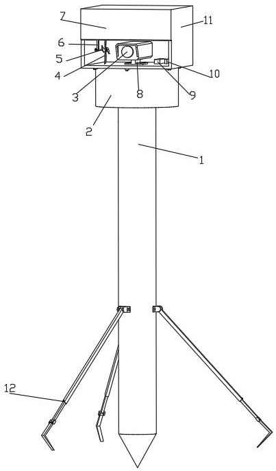
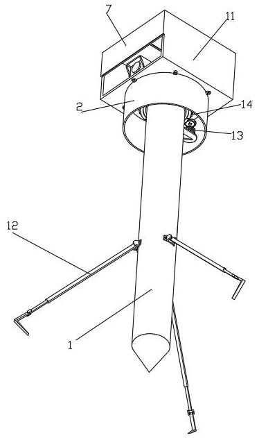
[0039] Such as Figure 1-8 A surface change detection device based on remote sensing image processing is shown, including a cone rod 1 and a camera 3. The outer wall of the lower end of the cone rod 1 is evenly fixed and connected along the circumferential direction with a reinforcement structure 12 for reinforcement of the cone rod 1. The reinforcement structure 12 includes The first U-shaped plate 1201, the cover plate 1202, the fixing bolt 1203, the slide plate 1204, the L-shaped fixed teeth 1205 and the second U-shaped fast 1206, the first U-shaped plate 1201 and the tapered rod 1 are fixedly connected by bolts, and the first U-shaped The plate 1201 is connected with the sleeve plate 1202 through the rotating shaft fixedly connected, and the sleeve plate 1202 is fitted and slidably connected with the slide plate 1204 through the opened square sliding hole. The bottom of 1204 is fixedly connected with a second U-shaped fastening 1206, and the bottom of the second U-shaped f...

Embodiment 2

[0041] Embodiment 2 is a further improvement to Embodiment 1.

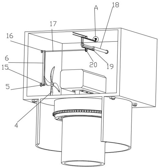
[0042] Such as Figure 1-8 A surface change detection device based on remote sensing image processing is shown, including a cone rod 1 and a camera 3. The outer wall of the lower end of the cone rod 1 is evenly fixed and connected along the circumferential direction with a reinforcement structure 12 for reinforcement of the cone rod 1. The reinforcement structure 12 includes The first U-shaped plate 1201, the cover plate 1202, the fixing bolt 1203, the slide plate 1204, the L-shaped fixed teeth 1205 and the second U-shaped fast 1206, the first U-shaped plate 1201 and the tapered rod 1 are fixedly connected by bolts, and the first U-shaped The plate 1201 is connected with the sleeve plate 1202 through the rotating shaft fixedly connected, and the sleeve plate 1202 is fitted and slidably connected with the slide plate 1204 through the opened square sliding hole. The bottom of 1204 is fixedly connected with a second...

Embodiment 3

[0045] Embodiment 3 is a further improvement to Embodiment 1.

[0046] Such as Figure 1-8 A surface change detection device based on remote sensing image processing is shown, including a cone rod 1 and a camera 3. The outer wall of the lower end of the cone rod 1 is evenly fixed and connected along the circumferential direction with a reinforcement structure 12 for reinforcement of the cone rod 1. The reinforcement structure 12 includes The first U-shaped plate 1201, the cover plate 1202, the fixing bolt 1203, the slide plate 1204, the L-shaped fixed teeth 1205 and the second U-shaped fast 1206, the first U-shaped plate 1201 is connected with the cover plate 1202 through the rotating shaft fixedly connected, and the sleeve The plate 1202 is fitted and slidably connected with a slide plate 1204 through the square slide hole provided, the outer wall of the bottom of the cover plate 1202 is threaded with a fixing bolt 1203 for fixing the slide plate 1204, and the bottom of the s...


PUM


Abstract

The invention relates to ground surface change detection equipment based on remote sensing image processing, and belongs to the technical field of geological disaster monitoring and early warning technologies and monitoring equipment, and the equipment comprises a conical rod which is provided with a reinforcing structure; the conical rod is provided with a rotating structure, the rotating structure comprises a driving motor, a first gear ring, a supporting bearing, a third gear ring and a supporting sleeve, the driving motor is provided with the third gear ring, a bearing bearing is connectedwith the conical rod, the bearing bearing is provided with the first gear ring, the first gear ring is meshed with the third gear ring, and the bearing bearing is provided with the supporting sleevewhich is provided with a protective cover. The protective cover is provided with a supporting frame, a controller and a signal transceiver, the supporting frame is provided with a camera, the protective cover is provided with a baffle, the baffle is provided with a sliding groove, the baffle is provided with a sliding plate, and the protective cover is provided with an adjusting structure. The camera shoots the ground surface and transmits the ground surface to the monitoring site bureau scientific research institute through the controller and the signal transceiver. The monitoring site bureauscientific research institute monitors the ground surface in real time through the remote sensing image processing technology for detection, monitoring work is simple, and monitoring cost is reduced.

Description

technical field [0001] The invention relates to the technical field of geological disaster monitoring and early warning technology and monitoring equipment, in particular to a surface change detection equipment based on remote sensing image processing. Background technique [0002] Geological disasters are referred to as geological disasters. Natural disasters that are mainly caused by geological dynamic activities or abnormal changes in the geological environment. Under the action of the earth's internal dynamics, external dynamics or man-made geological dynamics, the earth has abnormal energy release, material movement, deformation and displacement of rock and soil, and abnormal changes in the environment, etc., which endanger human life, property, life and economic activities or destroy human beings. Developmental resources, environmental phenomena or processes. Unfavorable geological phenomena are usually called geological disasters, which refer to geological events th...

Claims


Application Information

Patent Timeline
Patent Type & Authority Applications(China)
IPC IPC(8): G01C11/02
CPCG01C11/02
Inventor 马新国
Owner 马新国
Learn More