Supercharge Your Innovation With Domain-Expert AI Agents!

Object distance positioning system and method in specific area

A positioning system and object distance technology, applied in positioning, radio wave measurement systems, measurement devices, etc., can solve the problems of not considering LED errors or failures, ignoring interference, not considering the influence of light intensity signals, etc., to avoid interference and The effect of faults, avoiding light intensity interference, and high-precision object distance positioning

Active Publication Date: 2021-03-09
HANGZHOU SHILUAN TECH
View PDF6 Cites 1 Cited by
  • Summary
  • Abstract
  • Description
  • Claims
  • Application Information

AI Technical Summary

Problems solved by technology

[0008] However, the applicant found in practice that the above-mentioned visible light positioning technology proposed by the prior art is based on the fact that the target to be positioned is in a relatively static state, or although the target to be positioned can move, the positioning requires the target to be positioned and the corresponding LED The light source lamp group is in a temporary stable static state; in addition, most of the existing technologies are based on multi-LED lamp groups, that is, at least three or more LED light intensity signals are required to complete the positioning; more importantly, most of the existing technologies In addition to the current LED lamp group, the influence of the light intensity signal of other LED lamp groups that are not within the positioning range is not considered, that is, the interference is ignored, but this phenomenon exists widely in practice; finally, the existing technology does not Consider the situation that the LEDs within the current positioning range have errors or failures
[0009] All in all, most of the existing positioning technologies exist at the theoretical modeling level, and there are various defects in practical applications

Method used


Image

  • Object distance positioning system and method in specific area
  • Object distance positioning system and method in specific area
  • Object distance positioning system and method in specific area

Examples


Embodiment Construction

[0058] In the following, the invention will be further described in conjunction with the accompanying drawings and specific embodiments.

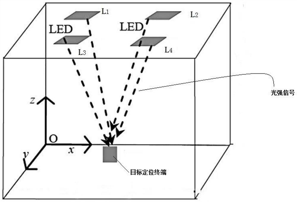
[0059] see figure 1 , as described in the background technology, the prior art generally requires at least four LED light sources L for indoor lighting 1 -L 4 They are symmetrically arranged on the ceiling at equal intervals, and the light radiation areas formed by different LEDs overlap each other to ensure that the target positioning terminal can receive the light intensity signal information from different LEDs at the same time. The target positioning terminal realizes position estimation based on the received reference information through photoelectric conversion, and the parameter required for positioning based on the TD OA principle is the time delay difference of signal transmission between the LED sending end and the positioning terminal. The number of LEDs participating in positioning will have an impact on positioning performanc...


PUM


Abstract

The invention provides an object distance positioning system and method in a specific area. The positioning system comprises a plurality of groups of LED light source emitters, a plurality of proximity detectors for controlling each group of LED light source emitters, and a target positioning terminal. The target positioning terminal comprises a photoelectric detector and a Bluetooth emitter. Theproximity detector detects the proximity degree of the target positioning terminal and the LED light source emitter to determine a target proximity controller; N LED light sources in the LED light source emitters of the corresponding groups are controlled to emit a plurality of different light intensity signals in different time slots by using a target proximity controller; and the target positioning terminal adopts a positioning algorithm to position the current position of the target positioning terminal, and displays the current position on a human-computer interaction interface of the target positioning terminal. According to the technical scheme, high-precision object distance positioning can be realized under the condition of LED change, and interference and faults are avoided.

Description

technical field [0001] The invention belongs to the technical field of indoor precise positioning, and in particular relates to a positioning system and method for object distance in a specific area. Background technique [0002] With the rapid development of the Internet of Things and modern communication technology, spatial positioning technology based on location information has become an indispensable and important technology in people's production and life. Since indoor GPS satellite signals are blocked by buildings, the speed and accuracy of positioning Serious decline, unable to meet the needs of indoor positioning. Therefore, scholars at home and abroad have conducted a lot of research on indoor positioning technology, and developed indoor positioning systems based on wireless electromagnetic waves, such as Bluetooth infrared laser WLAN ultra-wideband and ultrasonic indoor positioning technologies, but These indoor positioning technologies also have their own limitat...

Claims


Application Information

Patent Timeline
Patent Type & Authority Applications(China)
IPC IPC(8): G01S5/16G01S5/00
CPCG01S5/0009G01S5/16
Inventor 黄宇张晓杰任勇
Owner HANGZHOU SHILUAN TECH
Features
  • R&D
  • Intellectual Property
  • Life Sciences
  • Materials
  • Tech Scout
  • Unparalleled Data Quality
  • Higher Quality Content
  • 60% Fewer Hallucinations
Learn More