
I2C link management system and method

A link management and link technology, applied in the direction of electrical digital data processing, instruments, etc., can solve the problems of low I2C management efficiency and poor stability

Active Publication Date: 2021-03-09
INSPUR SUZHOU INTELLIGENT TECH CO LTD
View PDF2 Cites 1 Cited by
  • Summary
  • Abstract
  • Description
  • Claims
  • Application Information

AI Technical Summary

Problems solved by technology

[0005] This application provides an I2C link management system and method to solve the problem that the I2C link architecture in the prior art makes I2C management less efficient and more stable bad question

Method used


Image

  • I2C link management system and method
  • I2C link management system and method
  • I2C link management system and method

Examples


Embodiment 1

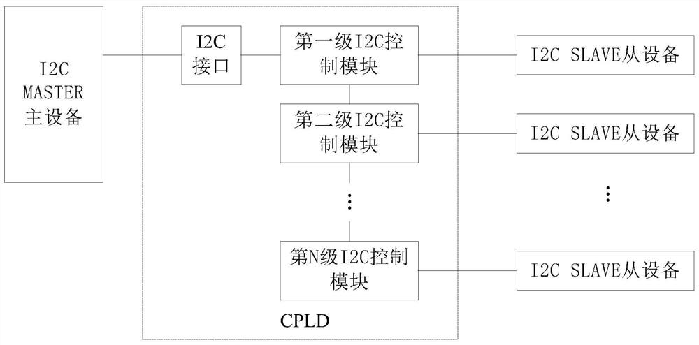
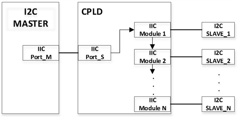
[0056] see figure 2 , figure 2 It is a schematic structural diagram of an I2C link management system provided by the embodiment of the present application. Depend on figure 2 It can be seen that the I2C link management system in this embodiment mainly includes: one I2C MASTER master device, multiple I2C SLAVE slave devices, and a CPLD is set between the I2C MASTER master device and the multiple I2C SLAVE slave devices. The CPLD of this embodiment includes: an I2C interface and a plurality of I2C control modules, which are sequentially connected in series, and any I2C control module is connected to an I2C SLAVE slave device, and one end of the I2C interface is connected to the I2C MASTER master device The control end of the I2C interface is connected to the first-level I2C control module among the plurality of I2C control modules. That is, in multiple I2C control modules, except for the first-level I2C control module, the output terminal of the previous I2C control module...

Embodiment 2

[0070] exist Figure 2-Figure 5 On the basis of the illustrated embodiment see Figure 6 , Figure 6 It is a schematic flowchart of an I2C link management method provided by the embodiment of the present application. The I2C link management method in this embodiment is mainly applied to the above-mentioned I2C link management system. Depend on Figure 6 It can be seen that the I2C link management method in this embodiment mainly includes the following processes:

[0071] S1: Continuously collect the I2C_SDA_IN signal of any I2C control module. Among them, the I2C_SDA_IN signal is the input data signal.

[0072] S2: Determine whether the I2C_SDA_IN signal is low level.

[0073] If the I2C_SDA_IN signal is low, the Figure 6 It can be seen that step S3 is further executed: judging whether the time for which the I2C_SDA_IN signal remains at a low level is ≥ a set time.

[0074] If the time for which the I2C_SDA_IN signal remains at a low level ≥ the set time, execute step...


PUM


Abstract

The invention discloses an I2C link management system and method, and the system comprises an I2C MASTER master device, a plurality of I2C SLAVE slave devices and a CPLD; the CPLD comprises an I2C interface and a plurality of I2C control modules, wherein each I2C control module is matched with one I2C SLAVE slave device, the I2C control modules are sequentially connected in series, one end of theI2C interface is connected with the control end of the I2C MASTER master device, and the other end is connected with a first-stage I2C control module in the plurality of I2C control modules. The method comprises the following steps: continuously acquiring an I2CSDAIN signal of any I2C control module; judging whether the level is low or not; if so, judging whether the time for keeping the low levelis greater than or equal to the set time or not; if so, judging that an I2C link where the I2CSDAIN signal is located has a hang-up phenomenon; when the I2C link where the I2CSDAIN signal is locatedis suspended, disconnecting the link between the I2C link where the I2CSDAIN signal is located and the rear-end I2C SLAVE slave device; otherwise, collecting the I2CSDAIN signal again; if the level isthe high level, resetting the time for keeping the low level. Through the I2C link management method and device, the I2C link management efficiency and stability can be effectively improved.

Description

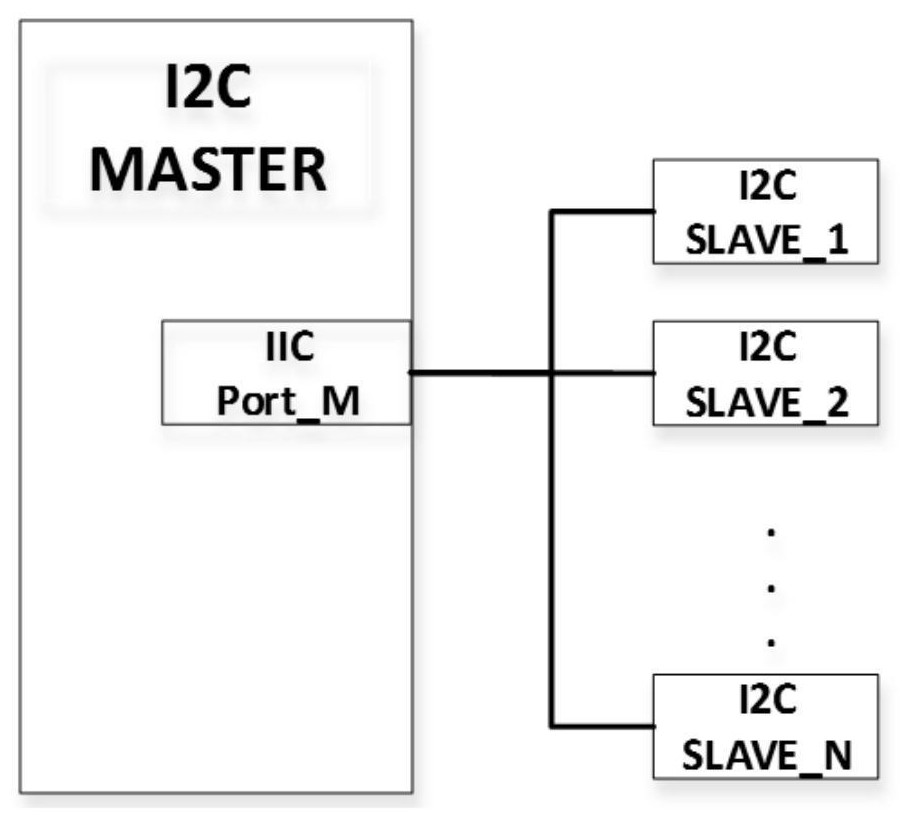
technical field [0001] The present application relates to the technical field of server I2C (Inter-Integrated Circuit, bus used to connect microcontrollers and peripheral devices) bus architecture design, and in particular to an I2C link management system and method. Background technique [0002] I2C is a master-slave two-wire serial communication bus commonly used in servers. With the development of server technology, more and more information needs to be monitored in the service system. Correspondingly, the I2C slave devices are increasing day by day. How to design the I2C link architecture and manage the I2C link so as to improve the working efficiency of the I2C link is an important technical issue. [0003] The current I2C bus link architecture can be found in figure 1 shown. figure 1 Among them, I2C MASTER (I2C master controller) means: the master controller in the IIC link can connect multiple IIC slave devices, monitor the slave device information in the link and ...

Claims


Application Information

Patent Timeline
Patent Type & Authority Applications(China)
IPC IPC(8): G06F13/42
CPCG06F13/4291
Inventor 张瑜
Owner INSPUR SUZHOU INTELLIGENT TECH CO LTD
Learn More