A kind of identification equipment allocation verification method, device and electronic equipment

A device allocation and identification technology, applied in the computer field, can solve problems such as getting lost and not being found.

Active Publication Date: 2021-04-27
北京博能科技股份有限公司
View PDF5 Cites 0 Cited by
  • Summary
  • Abstract
  • Description
  • Claims
  • Application Information

AI Technical Summary

Problems solved by technology

[0002] At present, in places with relatively dense traffic such as large hubs and large shopping malls, at the beginning of project design or in the operation stage of project construction completion, in order to avoid the situation where people get lost and cannot find their destination, it is necessary to identify facilities, equipment, signs, etc. Reasonable allocation of equipment, but due to the subjectivity of the allocation of identification equipment, it is difficult to avoid the situation where pedestrians get lost because they cannot see the instructions of the identification equipment after the installation of identification equipment in crowded places, so the rationality of the allocation of identification equipment needs to be checked verify

Method used


Image

  • A kind of identification equipment allocation verification method, device and electronic equipment
  • A kind of identification equipment allocation verification method, device and electronic equipment
  • A kind of identification equipment allocation verification method, device and electronic equipment

Examples


Embodiment 1

[0045] The identification device distribution verification method proposed in this embodiment is executed by a server.

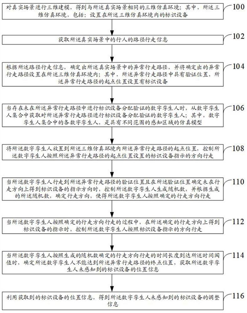
[0046] see figure 1 As shown in the flow chart of a verification method for identification device allocation, this embodiment proposes a identification device allocation verification method, which can specifically perform the following steps:

[0047] Step 100, perform three-dimensional modeling on the real scene to obtain the same three-dimensional simulation environment as the real scene; wherein, the three-dimensional simulation environment includes: an identification device set in the three-dimensional simulation environment.

[0048] In the above step 100, in order to perform three-dimensional modeling on the real scene, obtain the same three-dimensional simulation environment as the real scene, and convert the real scene into a virtual three-dimensional simulation environment. And the identification equipment set in the real scene is also set in the 3...

Embodiment 2

[0127] This embodiment proposes an identification device allocation verification device, which is used to execute the identification device allocation verification method described in Embodiment 1 above.

[0128] see figure 2 Shown is a schematic structural diagram of an identification equipment allocation verification device. This embodiment proposes an identification equipment allocation verification device, including:

[0129] The modeling module 400 is used to perform three-dimensional modeling on the real scene to obtain the same three-dimensional simulation environment as the real scene; wherein, the three-dimensional simulation environment includes: an identification device arranged in the three-dimensional simulation environment;

[0130] An acquisition module 402, configured to acquire path walking information of pedestrians in the real scene;

[0131] The first processing module 404 is configured to determine the abnormal walking path in the real scene according to...

Embodiment 3

[0151] This embodiment proposes a computer-readable storage medium, where a computer program is stored on the computer-readable storage medium, and when the computer program is run by a processor, the steps of the identification device allocation verification method described in the above-mentioned embodiment 1 are executed. For specific implementation, reference may be made to Method Embodiment 1, which will not be repeated here.

[0152] Also, see Figure 5 Shown is a schematic structural diagram of an electronic device. This embodiment also proposes an electronic device that includes a bus 51 , a processor 52 , a transceiver 53 , a bus interface 54 , a memory 55 and a user interface 56 . The electronic device described above includes a memory 55 .

[0153] In this embodiment, the above-mentioned electronic device further includes: one or more programs stored on the memory 55 and operable on the processor 52, configured so that the above-mentioned one or more programs are e...


PUM


Abstract

The present invention provides a verification method, device and electronic equipment for identification equipment allocation, which can set the abnormal walking path in the real scene in the same three-dimensional simulation environment as the real environment, and use digital twins with different perception area ranges according to the The indication of the identification equipment in the abnormal walking path Walk in the abnormal walking path, verify whether the identification equipment set in the real scene is valid, and when it is determined that the digital twin cannot reach the end position of the abnormal walking path under the guidance of the identification equipment , can also give the adjustment information of the identification equipment that the digital twin is not aware of, so that the validity of the identification equipment set in the real scene can be verified accurately and objectively.

Description

technical field [0001] The present invention relates to the field of computer technology, in particular to a method, device and electronic device for verifying the distribution of identification equipment. Background technique [0002] At present, in places with relatively dense traffic such as large hubs and large shopping malls, at the beginning of project design or in the operation stage of project construction completion, in order to avoid the situation where people get lost and cannot find their destination, it is necessary to identify facilities, equipment, signs, etc. Reasonable allocation of equipment, but due to the subjectivity of the allocation of identification equipment, it is difficult to avoid the situation where pedestrians get lost because they cannot see the instructions of the identification equipment after the installation of identification equipment in crowded places, so the rationality of the allocation of identification equipment needs to be checked ve...

Claims


Application Information

Patent Timeline
Patent Type & Authority Patents(China)
IPC IPC(8): G06Q30/02G06T17/10
CPCG06Q30/0281G06T17/10
Inventor 齐焕然王雪锋王珏李品
Owner 北京博能科技股份有限公司
Why Eureka
Try Eureka