
Power system transformer winding automatic production equipment

A transformer winding and power system technology, applied in the direction of inductance/transformer/magnet manufacturing, circuits, electrical components, etc., can solve problems such as cumbersome winding methods and affecting winding efficiency

Active Publication Date: 2021-03-09
丽水正阳电力建设有限公司
View PDF22 Cites 2 Cited by
  • Summary
  • Abstract
  • Description
  • Claims
  • Application Information

AI Technical Summary

Problems solved by technology

[0003] Now the existing winding method is cumbersome and troublesome, and requires human intervention to control the direction and distance of the winding, which affects the efficiency of the winding. Therefore, we propose an automatic production equipment for power system transformer windings.

Method used


Image

  • Power system transformer winding automatic production equipment
  • Power system transformer winding automatic production equipment
  • Power system transformer winding automatic production equipment

Examples


Embodiment Construction

[0018] The following will clearly and completely describe the technical solutions in the embodiments of the present invention with reference to the accompanying drawings in the embodiments of the present invention. Obviously, the described embodiments are only some, not all, embodiments of the present invention. Based on the embodiments of the present invention, all other embodiments obtained by persons of ordinary skill in the art without making creative efforts belong to the protection scope of the present invention.

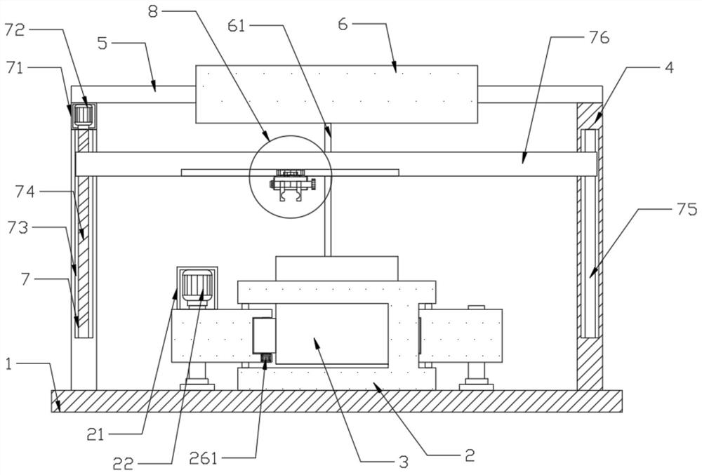
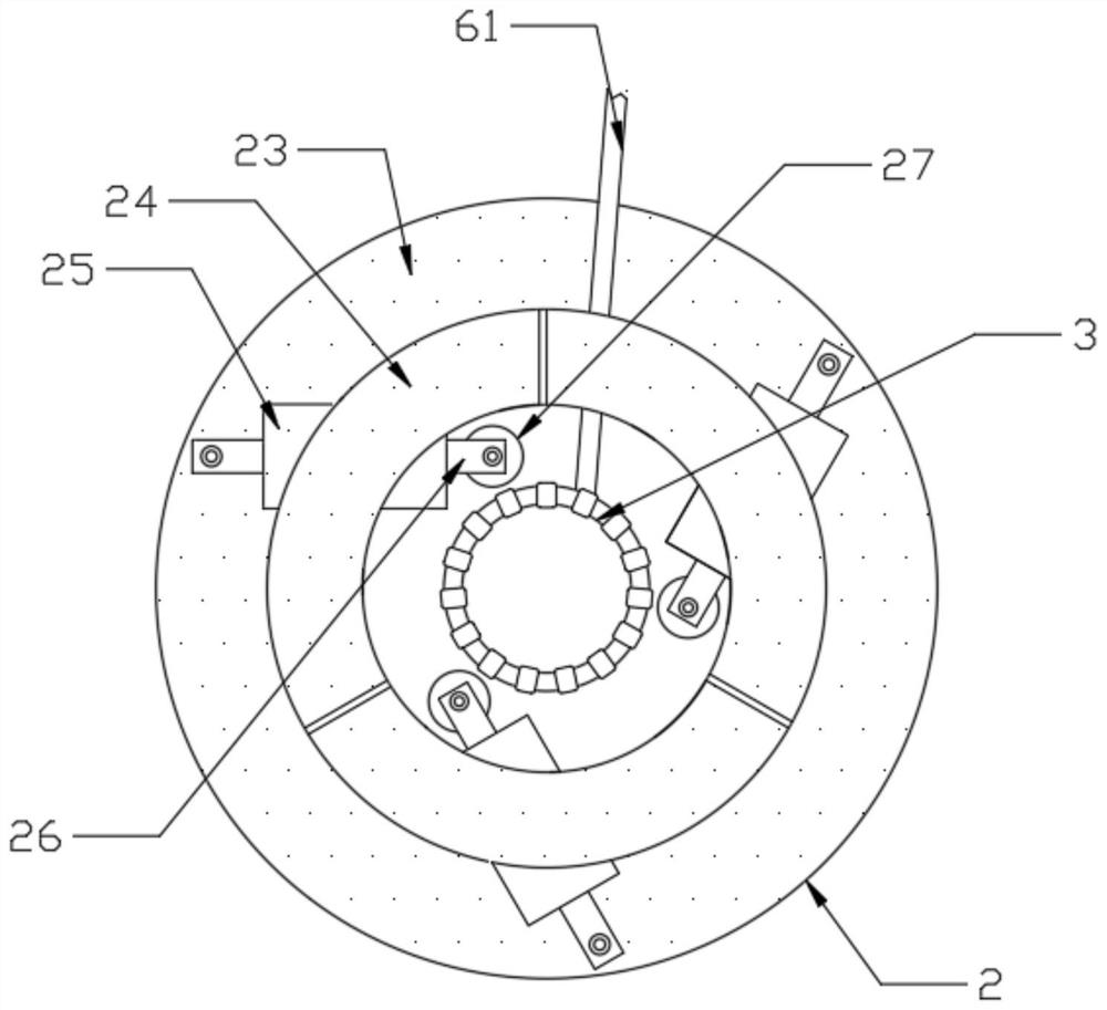
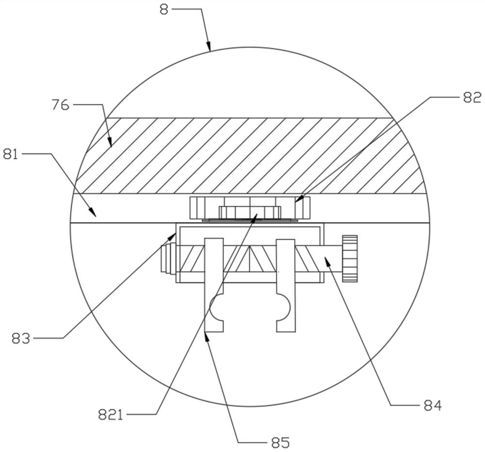
[0019] see figure 1 , an automatic production equipment for power system transformer windings in the figure, including a base 1 and a fixed plate 4, two fixed plates 4 are symmetrically fixed on the top of the base 1, and the top of the base 1 is located between the two fixed plates 4. There is a winding assembly 3, the top of the fixed plate 4 is provided with an unwinding roller 6, and a winding wire 61 is wound on the surface of the unwinding roller 6, and ...


PUM


Abstract

The invention discloses power system transformer winding automatic production equipment, and the equipment comprises a base and fixed plates; the two fixed plates are symmetrically fixed to the top ofthe base, a winding assembly is arranged at the position, located between the two fixed plates, of the top of the base, an unwinding roller is arranged at the tops of the fixed plates, and a windingwire is connected to the surface of the unwinding roller in a winding mode; the winding wire is connected to the surface of the winding assembly in a winding mode, a clamping mechanism capable of driving the winding assembly to rotate for winding is arranged at the position, corresponding to the winding assembly, of the top of the base, the clamping mechanism is in transmission connection with thewinding assembly, and a lifting mechanism capable of moving in a lifting mode is arranged in the fixed plate. Under the action of the clamping mechanism, the equipment achieves the stable clamping effect on the winding assembly, and under the action of the lifting mechanism and the wire clamping mechanism, the equipment achieves the smoothness of the winding assembly and the winding wire in the winding process, and knotting is not likely to be formed.

Description

technical field [0001] The invention relates to the technical field of transformer winding production, in particular to automatic production equipment for power system transformer windings. Background technique [0002] The power transformers produced in my country basically have only one structural type, that is, core transformers, so the windings all adopt concentric structures. The so-called concentric winding means that on any cross-section of the iron core column, the winding is sheathed on the outside of the iron core column with the same cylindrical wire. In general, the low voltage winding is always placed inside close to the iron core, and the high voltage winding is placed outside. There must be a certain insulation gap and heat dissipation channel (oil passage) between the high voltage winding and the low voltage winding, as well as between the low voltage winding and the iron core column, and they are separated by insulating cardboard tubes. [0003] The existi...

Claims


Application Information

Patent Timeline
IPC IPC(8): H01F41/09H01F41/082
CPCH01F41/09H01F41/082
Inventor 蒋中平徐清波张飞勇叶向阳潘明华吴建灵殷明
Owner 丽水正阳电力建设有限公司
Learn More