Clamping mechanism and transfer device
A technology of a clamping mechanism and a transfer device, which is applied in laboratory utensils, chemical instruments and methods, and supporting utensils, etc., can solve the problems of polluted capillaries and low work efficiency.
- Summary
- Abstract
- Description
- Claims
- Application Information
AI Technical Summary
Problems solved by technology
Method used
Image
Examples
Embodiment 1
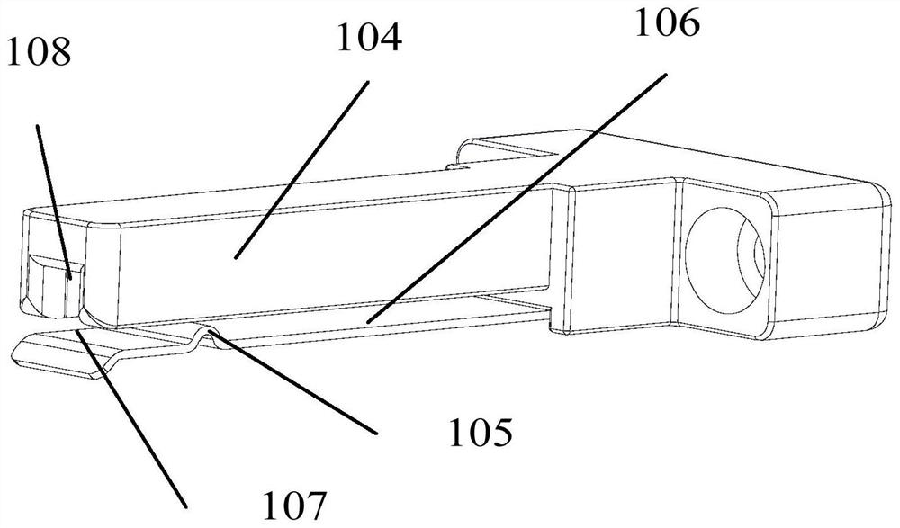
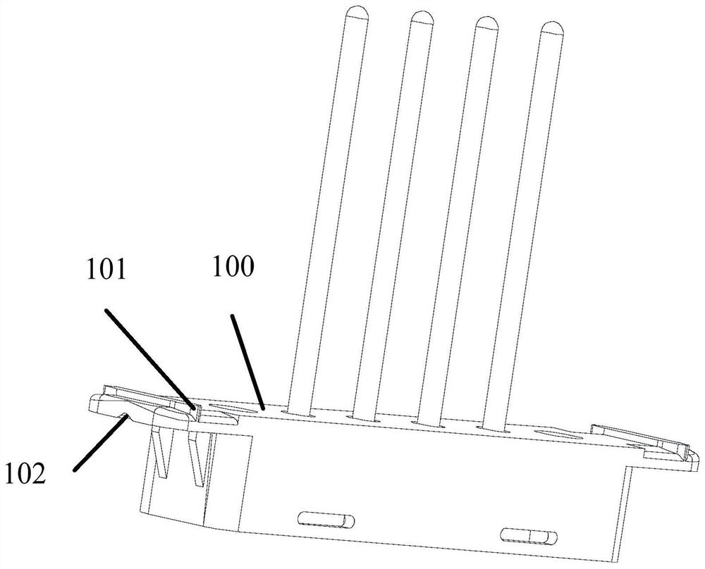
[0057] The present application provides a clamping mechanism, which can clamp the capillary holder 100 on the reagent box 119, combined with figure 2 As shown, the top end of the capillary holder 100 has a protrusion 101, and its bottom end has a groove 102; figure 1 As shown, the clamping mechanism includes a clamping jaw 104 and a supporting plate 106; the supporting plate 106 is located below the clamping jaw 104, and is at a preset distance from the clamping jaw 104, so that the clamping jaw 104 and the A clamping space 107 is formed between the supporting plates 106; furthermore, the clamping end of the clamping jaw 104 is provided with a clamping groove 108 along its length direction, preferably, the length of the clamping groove 108 is consistent with the protrusion 101 are equal in length; the supporting plate 106 is provided with a limiting protrusion 105 corresponding to the position of the groove 102 .
[0058] In the actual use process, when passing through the s...
Embodiment 2
[0062] The second embodiment is an improvement on the basis of the above embodiment. The technical content disclosed in the above embodiment will not be described repeatedly, and the content disclosed in the above embodiment also belongs to the content disclosed in the second embodiment.
[0063] Considering that the capillary holder 100 is provided with a plurality of capillaries at intervals, that is to say, the width of the capillary holder 100 is affected by the number of capillaries. If the capillary holder 100 is too wide, in order to ensure the stable clamping of the capillary holder 100 by the clamping mechanism, In this embodiment, there are multiple jaws 104 and supporting plates 106; multiple jaws 104 are in one-to-one correspondence with multiple supporting plates 106, that is, using multiple jaws 104 and a plurality of supporting plates 106 realize the stable clamping of multi-point positioning for the capillary holder 100 .
[0064] Specifically, the plurality of...
Embodiment 3
[0067] The third embodiment is an improvement on the basis of the above embodiment. The technical content disclosed in the above embodiment will not be described repeatedly, and the content disclosed in the above embodiment also belongs to the content disclosed in the third embodiment.
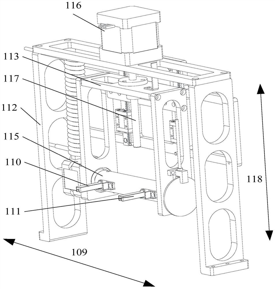
[0068] In the actual experimental process, after the capillary support 100 is clamped by the clamping mechanism, the capillary support 100 needs to be covered with an end cover 103 to realize the sealing of the capillary support 100; When covering the end cap 103 of the capillary holder 103, it is necessary to drive the clamping mechanism holding the capillary holder 100 to move along the second direction 118 (moving close to the end cover 103), so as to realize the covering operation of the end cap 103 of the capillary holder 100.
[0069] Based on the above problems, in this embodiment, the clamping mechanism also includes a first drive assembly, the first drive assembly includes a fixed cyli...
PUM
 Abstract
Description
Claims
Application Information
 - R&D
- Intellectual Property
- Life Sciences
- Materials
- Tech Scout
- Unparalleled Data Quality
- Higher Quality Content
- 60% Fewer Hallucinations
Browse by: Latest US Patents, China's latest patents, Technical Efficacy Thesaurus, Application Domain, Technology Topic, Popular Technical Reports.
© 2025 PatSnap. All rights reserved.Legal|Privacy policy|Modern Slavery Act Transparency Statement|Sitemap|About US| Contact US: help@patsnap.com


