Operating mechanism and crank arm thereof

A technology of operating mechanism and crank arm, applied in the direction of contact drive mechanism, etc., can solve problems such as complex structure, achieve the effect of reducing processing amount, increasing matching position, and simple structure

Pending Publication Date: 2021-03-09
HENAN SENYUAN ELECTRIC CO LTD
View PDF12 Cites 0 Cited by
  • Summary
  • Abstract
  • Description
  • Claims
  • Application Information

AI Technical Summary

Problems solved by technology

[0005] The purpose of the present invention is to provide a crank arm, which can solve the problem of complicated structure in the prior art of the high versatility of the crank arm; another purpose of the present invention is to provide an operating mechanism using the crank arm, which has a structure simple advantage

Method used


Image

  • Operating mechanism and crank arm thereof

Examples


Embodiment Construction

[0036] The specific implementation of the operating mechanism and its crank arm in the present invention will now be described in conjunction with the accompanying drawings.

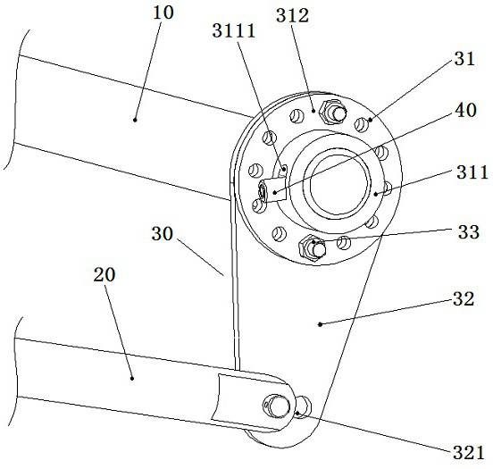
[0037] An embodiment of the operating mechanism in the present invention: the operating mechanism includes a driving shaft and a connecting rod as a follower, and a crank arm for transmitting power is connected between the driving shaft and the connecting rod, such as figure 1 As shown, the drive shaft 10 and the connecting rod 20 are arranged in a manner perpendicular to the axis, and a crank arm 30 is assembled at the end of the drive shaft 10 . The other end of the crank arm 30 is hinged with the connecting rod 20 .

[0038] The crank arm 30 is a split structure and mainly includes a crank arm plate 31 and a crank arm plate 32 . The structure of the crank disc 31 is similar to the structure of the flange in the prior art, including a bushing 311 matched with the drive shaft 10, and the bushing 311 is...


PUM


Abstract

The invention provides an operating mechanism and a crank arm thereof, and the crank arm comprises: a crank arm disc which is provided with a through hole in rotation stopping fit with a driving shaftin the operating mechanism; a crank arm plate, wherein a hole or an opening for avoiding a shaft sleeve in the driving shaft or the crank arm disc is formed in the crank arm plate, one of the crank arm disc and the crank arm plate is provided with a plurality of connecting holes arranged around the axial direction of the driving shaft, and the other one of the crank arm disc and the crank arm plate is provided with at least one adaptive hole corresponding to any one of the connecting holes, so that the connecting piece penetrates through the connecting holes and the adaptive holes to fix thecrank arm disc and the crank arm plate. The connecting position of the crank arm disc and the crank arm plate is changed to adapt to driving shafts and driven pieces with different arrangement relations, holes or openings are formed in the connecting lever plate, the positions of the crank arm plate are limited by the driving shafts or the crank arm disc, and the crank arm disc and the crank arm plate can be fixed only by enabling one connecting piece to penetrate through one set of connecting holes and one set of adapting holes, so that the processing amount of the adapting holes in the crankarm plate or the crank arm disc is reduced. Compared with the prior art, the machining amount is reduced, and the structure is simpler.

Description

technical field [0001] The invention relates to an operating mechanism and its crank arm. Background technique [0002] In the prior art, when the crank arm in the operating mechanism is assembled, it can rotate around the main shaft and change its relative position with the main shaft to adapt to the relative position of the main shaft and different followers, which is convenient for assembly and can improve the crank arm versatility. For example, the authorized announcement number is CN209183413U, and the patent document whose authorized announcement date is 2019.07.30 discloses an operating crank arm. The crank arm includes a crank arm plate and a crank arm plate. The anti-rotation structure is sleeved on the rotating shaft and rotates with the rotating shaft during use; at least two mounting positions for mounting the rotating arm plate are arranged on the rotating arm along its axial direction, and the rotating arm plate can be moved through the mounting position of th...

Claims


Application Information

Patent Timeline
Patent Type & Authority Applications(China)
IPC IPC(8): H01H3/46
CPCH01H3/46
Inventor 张智磊赵亚中仇文镖
Owner HENAN SENYUAN ELECTRIC CO LTD
Why Eureka
Try Eureka