Valve control system of light-operated converter valve and light trigger channel detection method

A channel detection and valve control system technology, applied in transmission systems, electromagnetic wave transmission systems, electrical components, etc., can solve problems such as low efficiency and secondary damage to optical fibers, so as to improve detection efficiency, solve low efficiency, and solve secondary problems. damage effect

Active Publication Date: 2021-03-09
XUJI GRP +4
View PDF4 Cites 2 Cited by
  • Summary
  • Abstract
  • Description
  • Claims
  • Application Information

AI Technical Summary

Problems solved by technology

[0004] The purpose of the present invention is to provide a detection method for light-triggered channels of light-controlled converter valves, which is used to solve the problems of low efficiency of light-triggered channel detection methods in the prior art and easy to cause secondary damage to optical fibers; at the same time, it also provides a The valve control system of the light-controlled converter valve is used to solve the problems of low efficiency of the light-triggered channel detection method in the prior art and easy to cause secondary damage to the optical fiber

Method used


Image

  • Valve control system of light-operated converter valve and light trigger channel detection method
  • Valve control system of light-operated converter valve and light trigger channel detection method

Examples


Embodiment Construction

[0022] The technical solution of the present invention will be further described below in conjunction with specific embodiments.

[0023] System embodiment:

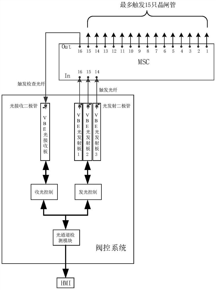
[0024] This embodiment provides a valve control system for light-controlled converter valves, the structure of which is as follows figure 1 As shown, it includes a light-emitting tube and a light-receiving tube; the light-emitting tube includes three light-emitting diodes, and the three light-emitting diodes are respectively arranged on the valve base electronics (Valve base electronics, VBE) system, that is, the light emitting diode of the valve control system Board 1, valve control system light emitting board 2 and valve control system light emitting board 3; the light receiving tube includes a light receiving diode, which is set on the valve control system light receiving board. The number of valve control system light emitting boards and valve control system light receiving boards increases according to the number o...


PUM


Abstract

The invention provides a valve control system of a light-operated converter valve and a light trigger channel detection method, and the detection method comprises the following steps: controlling anylight emitting tube in a light trigger channel to emit light during the power-off period of the converter valve, and transmitting the light emitted by the light emitting tube to a light receiving tubealong a trigger optical fiber, an MSC and a trigger check optical fiber, wherein the power failure of the converter valve means that the converter valve is not electrified and does not act; and comparing the transmitting light power of the light transmitting tube with the receiving light power of the light receiving tube, and if the ratio of the transmitting light power to the receiving light power is within a set range, indicating that the light triggering channel is normal. According to the technical scheme provided by the invention, each section of optical fiber in the light triggering channel does not need to be performed one by one, so that the detection efficiency can be improved, and the problem of low efficiency of the detection method is solved; and the optical fiber does not need to be repeatedly plugged and unplugged in the detection process, so that the problem of secondary damage to the optical fiber can be solved.

Description

technical field [0001] The invention belongs to the technical field of control of a light-controlled converter valve, and in particular relates to a valve control system of a light-controlled converter valve and a detection method for a light-triggered channel. Background technique [0002] The converter valve is the core equipment of HVDC power transmission. According to different control methods, the converter valve is generally divided into light-controlled converter valves and electronically controlled converter valves. The core device of the light-controlled converter valve is the light-controlled thyristor. The wavelength of the laser is directly triggered, and the optical trigger channel provides a transmission channel for the laser of a specific wavelength. The long-term stable and reliable operation of the optical trigger channel is a necessary condition for the long-term stable and reliable operation of the converter valve. [0003] When the converter valve is runn...

Claims


Application Information

Patent Timeline
Patent Type & Authority Applications(China)
IPC IPC(8): H04B10/079
CPCH04B10/07955Y02E60/60
Inventor 胡四全毛文喜范彩云韩坤周建华刘建邱文龙何慧雯王磊徐阳赵起超
Owner XUJI GRP
Why Eureka
Try Eureka