Auxiliary clamping device for turning steam turbine rotor on horizontal lathe

A steam turbine rotor and auxiliary clamping technology, which is applied in the direction of clamping device, positioning device, clamping, etc., can solve the problems of secondary injury to personnel and equipment, indentation on the finished surface of the rotor, and shaft channeling of copper gaskets, etc. Achieve the effect of avoiding the hidden danger of loosening, low cost and easy production and manufacturing

Active Publication Date: 2018-08-21
HARBIN TURBINE +1
View PDF9 Cites 0 Cited by
  • Summary
  • Abstract
  • Description
  • Claims
  • Application Information

AI Technical Summary

Problems solved by technology

[0003] The present invention solves the problem that the jaw clamping force of the existing steam turbine rotor in the process of clamping the rotor by the horizontal lathe will cause indentation and scratches on the finished surface of the rotor. In order to solve the problem of shaft channeling caused by copper gaskets between the copper gaskets and the loosening of copper gaskets, which will cause greater secondary damage to personnel and equipment, an auxiliary clamping device for turning steam turbine rotors on horizontal lathes is proposed.

Method used


Image

  • Auxiliary clamping device for turning steam turbine rotor on horizontal lathe
  • Auxiliary clamping device for turning steam turbine rotor on horizontal lathe
  • Auxiliary clamping device for turning steam turbine rotor on horizontal lathe

Examples


specific Embodiment approach 1

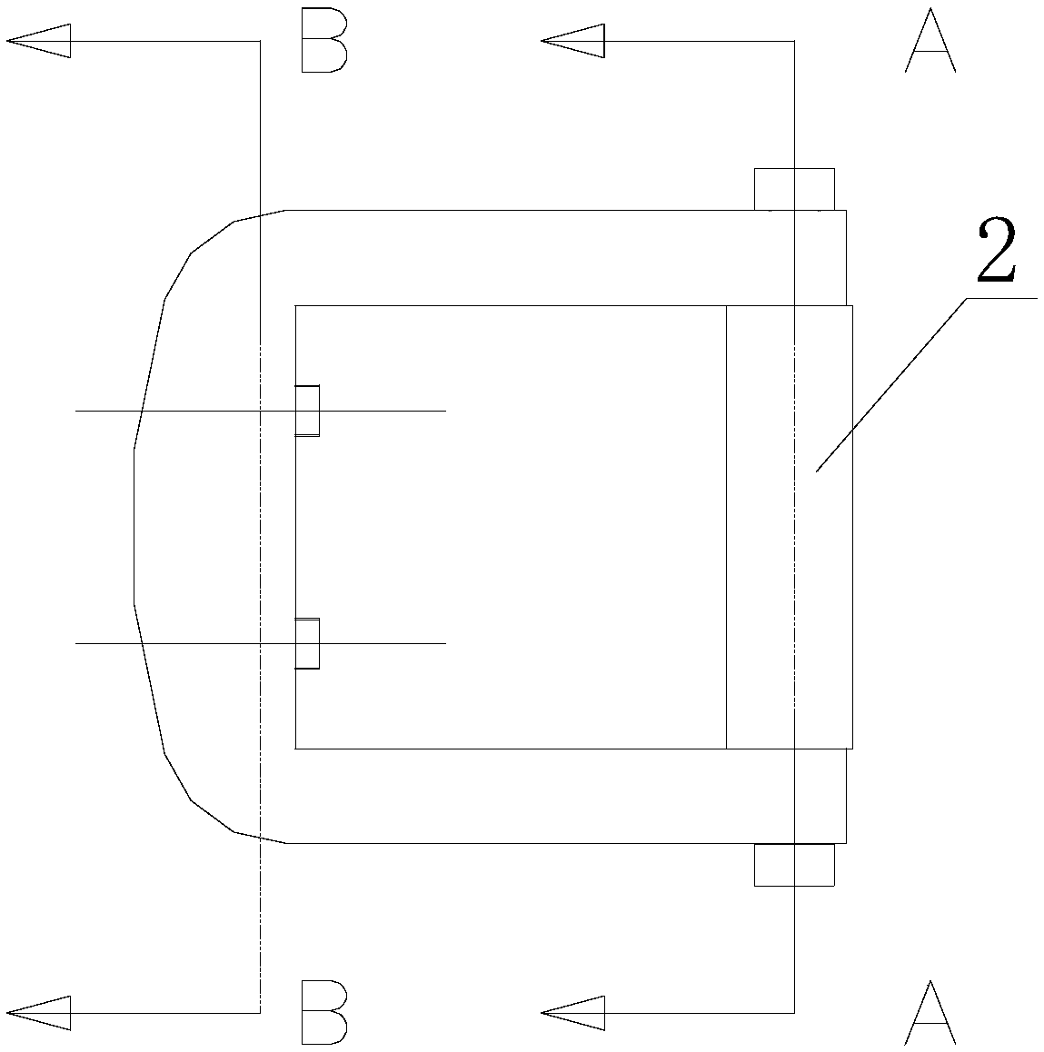
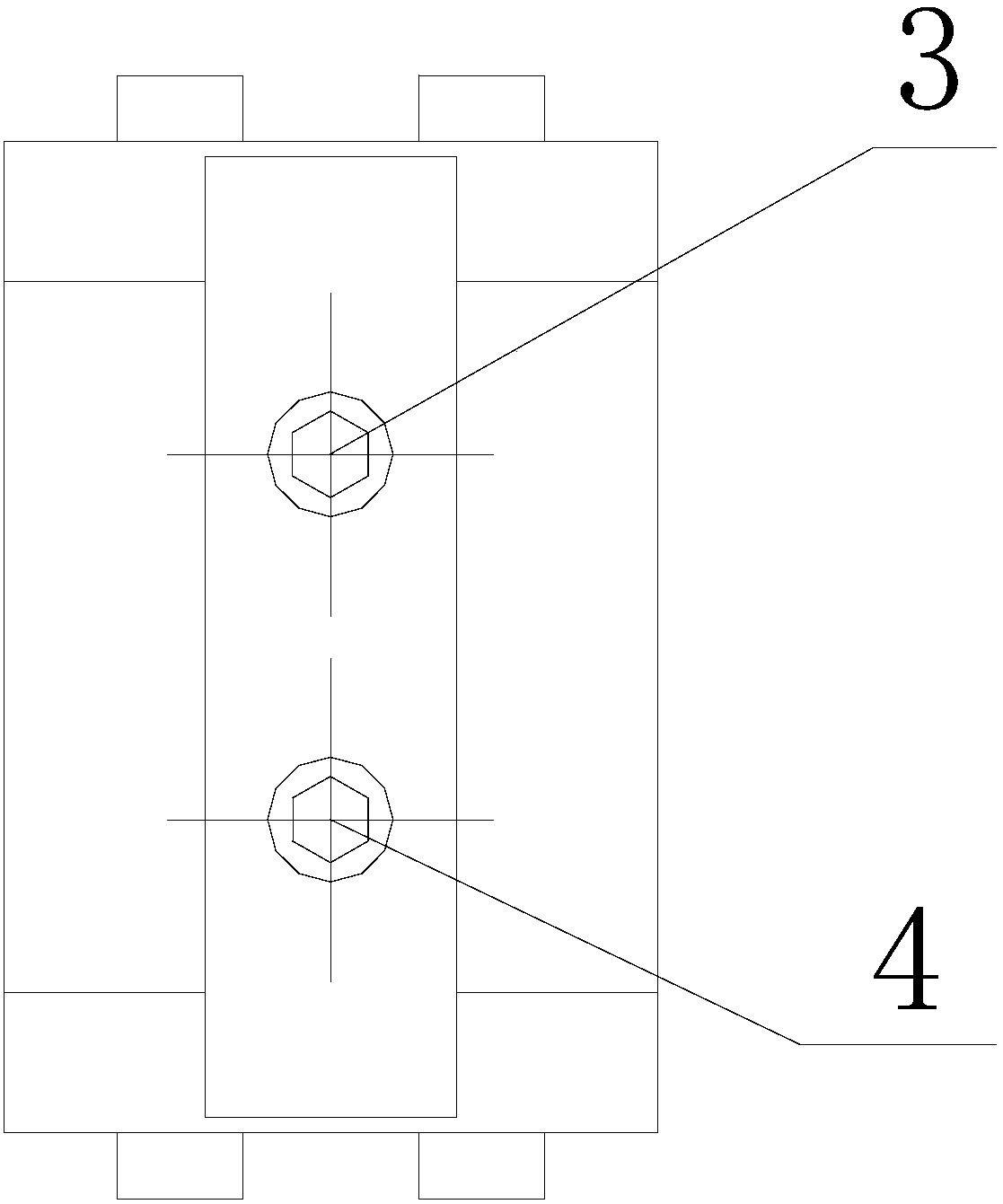
[0024] Specific implementation mode one: combine Figure 1-7 Describe this embodiment, this embodiment horizontal lathe turning steam turbine rotor auxiliary clamping device, this device consists of U-shaped plate 1, cuboid copper gasket 2, first bolt 3, second bolt 4, third bolt 5, The fourth bolt 6, the fifth bolt 7 and the sixth bolt 8 are formed;

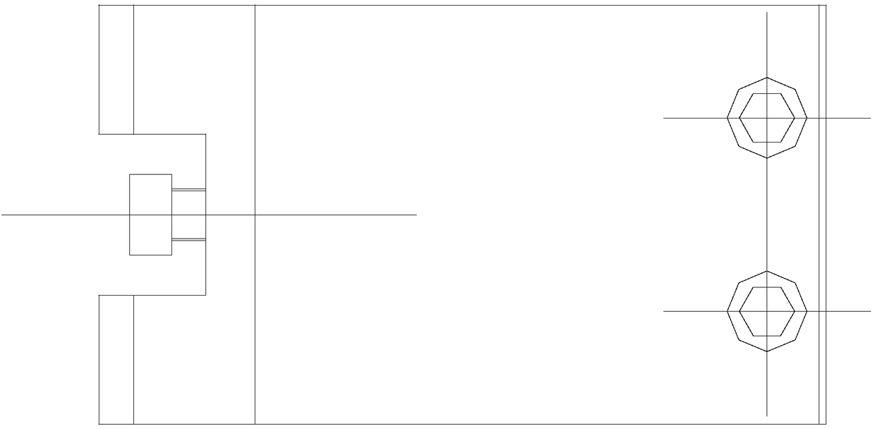
[0025] The cuboid copper gasket 2 is arranged in the opening of the U-shaped plate 1, and the inner surface of the U-shaped plate 1 and the inner surface of the rectangular parallelepiped copper gasket 2 are enclosed to form a cuboid hole; the rectangular parallelepiped copper gasket 2 and the inner surface of the U-shaped plate 1 Among the two contacting end faces, one of the end faces is provided with a first threaded blind hole 21 and a second threaded blind hole 22, and the other end face is provided with a third threaded blind hole 23 and a fourth threaded blind hole 24; The connecting line of the center of the blind hole ...

specific Embodiment approach 2

[0030] Specific implementation mode two: combination Image 6 This embodiment is described. The difference between this embodiment and the first embodiment is that the nut of the fifth bolt 7 and the nut of the sixth bolt 8 are arranged inside the elongated notch 11 . Other steps and parameters are the same as those in the first embodiment.

specific Embodiment approach 3

[0031] Specific implementation mode three: combination figure 1 This embodiment is described. The difference between this embodiment and the first or second embodiment is that the screw head of the fifth bolt 7 protrudes outside the first threaded through hole 13 . Other steps and parameters are the same as those in Embodiment 1 or 2.


PUM


Abstract

The invention provides an auxiliary clamping device used by a horizontal lathe for turning a steam turbine rotor and relates to the clamping device. The clamping device aims to solve the problems that in the machining process of an existing steam turbine rotor, jaw clamping force causes dents and scratches to a rotor fine machining face when a horizontal lathe clamps a rotor, a copper gasket between a jaw of the horizontal lathe and the fine machining face generates the axial channeling phenomenon, and higher personnel and equipment secondary harm is caused due to loosening of the copper gasket. The auxiliary clamping device comprises a U-shaped plate, a cuboid copper gasket and a plurality of bolts, and the cuboid copper gasket is arranged in an opening of the U-shaped plate. By means of the auxiliary clamping device, the problems that in the machining process of the existing steam turbine rotor, dents and scratches are caused to the fine machining face when the horizontal lathe clamps the rotor, the copper gasket between the jaw of the horizontal lathe and the fine machining face generates the axial channeling phenomenon, and higher personnel and equipment secondary harm is caused due to loosening of the copper gasket are solved, and the auxiliary clamping device is applicable to auxiliary clamping of the steam turbine rotor.

Description

technical field [0001] The invention relates to an auxiliary clamping device for turning a steam turbine rotor by a horizontal lathe. Background technique [0002] The steam turbine rotor generally uses a horizontal lathe during the processing process. The horizontal lathe generally adopts a clamping and supporting method for the rotor, that is, one side clamps the outer circle of the rotor, and the other side is supported by the hydraulic bracket on the shaft of the rotor. On the neck, the claws of the horizontal lathe are clamped at the outer circle of the rotor for finishing during finishing, and the clamping force of the claws will cause indentations and scratches on the finishing surface of the rotor, so it is usually used between the four claws and the finish machining Copper gaskets are added to the outer surface of the rotor to avoid damage to the outer circle of the rotor. However, due to the heavy weight of the rotor, the shaft system will have high sides and low d...

Claims


Application Information

Patent Timeline
Patent Type & Authority Patents(China)
IPC IPC(8): B23Q3/00
CPCB23Q3/00B23Q2703/10
Inventor 刘滨刚高岩田瑞军姜黎生常海滨
Owner HARBIN TURBINE
Why Eureka
Try Eureka