Part for a turbomachine centrifugal breather having a filtering mesh

A breather, centrifugal technology, applied in the direction of turbine/propulsion lubrication, centrifuge, engine components, etc., can solve the problem of restricting the best geometry, and achieve the effect of easy manufacturing

Active Publication Date: 2021-03-09
SAFRAN
View PDF24 Cites 0 Cited by
  • Summary
  • Abstract
  • Description
  • Claims
  • Application Information

AI Technical Summary

Problems solved by technology

[0007] With respect to the internal shape of the breather defining the ducts occupied by the air flow, the manufacturing process may then limit the possibilities for achieving the optimal geometry

Method used


Image

  • Part for a turbomachine centrifugal breather having a filtering mesh
  • Part for a turbomachine centrifugal breather having a filtering mesh
  • Part for a turbomachine centrifugal breather having a filtering mesh

Examples


Embodiment Construction

[0040] In the drawings, for the sake of illustration and clarity, scale and ratios have not been strictly adhered to.

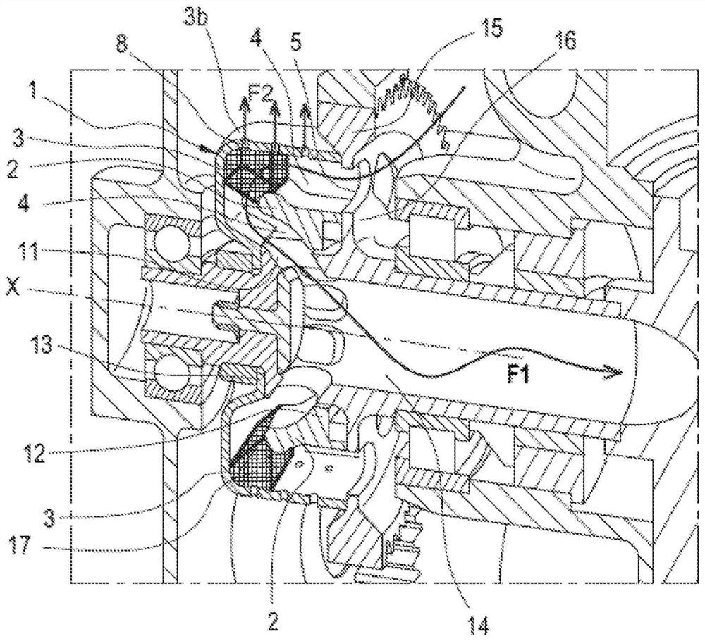
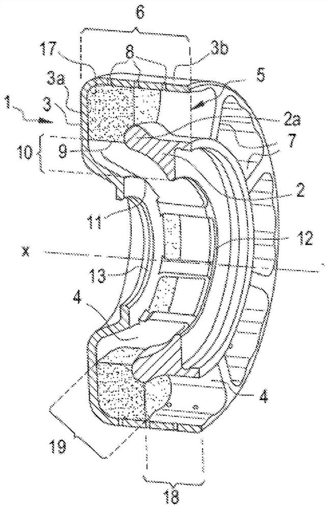
[0041] likefigure 1 As shown, the aerator using the invention comprises a movable part 1 rotating around a longitudinal axis of symmetry X. like figure 2 Shown in more detail, said movable part 1 comprises a structural part comprising a first housing 2 surrounded by a second housing 3 . The space between the two housings 2 , 3 forms a duct 4 rotating about the central axis of symmetry X for the circulation of the air / oil mixture to be separated.

[0042] The duct 4 comprises an axial inlet 5 for the entry of the air / oil mixture to be separated. This axial inlet 5 corresponds to one end of the first part 6 of the duct 4 which extends substantially axially for centrifuging the mixture. The first part 6 of the axially extending duct acts as a centrifuge housing, since at this first part of the axially extending duct the centrifugal force is exerted with maxi...


PUM

PropertyMeasurementUnit
lengthaaaaaaaaaa
sizeaaaaaaaaaa
diameteraaaaaaaaaa

Abstract

The invention relates to a part for a centrifugal breather for an air / oil mixture of a turbomachine, which is intended to rotate about a longitudinal axis of symmetry, forming an annular chamber for centrifugal separation of said mixture, the chamber also comprising at least one mesh structure that takes up at least one space in said duct which closes communication between an axial inlet and an internal radial outlet, characterized in that the mesh structure is formed by the spatial repetition, either in terms of the material or in terms of the space, of a single pattern produced by the interconnection of simple shapes to be chosen from spheres or ovoids and bars of constant section, in particular circles, rectangles or octagons, said pattern being designed such that the spaces between thematerial communicate so as to organize paths passing through the material in at least three dimensions of space forming a trihedron.

Description

technical field [0001] In particular, the invention relates to a centrifugal breather for a turbomachine. Background technique [0002] Turbines are complex systems that use many rotating components (turbines, compressors, etc.) that must be equipped with sealing devices. These seals are usually made of a labyrinth of pressurized air arranged near the rotating assembly. For this, the air is taken directly from the air duct of the turbine. This air is then passed through the turbine through the various labyrinths provided for this purpose, and then exhausted to the outside of the turbine to limit the pressure rise in other areas of the turbine (notably the reduction gearbox, accessory gearbox, etc.). This air passing through different areas of the turbine is laden with oil that cools and lubricates the bearings and pinions of the rotating components. In order to avoid the discharge of oily air, to reduce the ecological impact of the turbine, to reduce oil consumption and t...

Claims


Application Information

Patent Timeline
Patent Type & Authority Applications(China)
IPC IPC(8): F01M11/08B04B5/08B04B7/08B04B9/08F01D25/18F16H57/04B01D45/14F01M13/04F02C7/06F01M11/03
CPCF01M11/08F01D25/18B01D45/14F01M13/04F05D2260/602F01D25/16F05D2260/98F01M11/03F01M2013/0422F02C7/06F05D2220/32
Inventor 阿诺德·乔治斯·尼芬克尔本杰明·尼古拉斯·弗勒瑞格塞德里克·让·丹尼尔·普兰诺泽维尔·罗杰·贝特贝德-劳奎
Owner SAFRAN
Why Eureka
Try Eureka