
Anti-slip valve clamping device and valve clamping system

An anti-slip and valve technology, applied in the field of medical devices, can solve the problems of long axial size, easy slippage, cardiac dysfunction, etc., and achieve the effect of light weight and small overall size

Pending Publication Date: 2021-03-12
HANGZHOU VALGEN MEDTECH CO LTD
View PDF0 Cites 7 Cited by
  • Summary
  • Abstract
  • Description
  • Claims
  • Application Information

AI Technical Summary

Problems solved by technology

In order to ensure the clamping effect, it is necessary to use wider clamp arms. However, in the prior art, the two clamp arms of the valve clamp are fixed on the base in a mating manner and a connecting rod is used to drive the clamp arms to open and close. As a result, the size of the base of the clamp is relatively large, and multiple connecting rod parts also result in a long axial dimension of the clamp, requiring the use of a delivery sheath with a large diameter, which increases the difficulty of delivery; moreover, the connecting rod assembly and larger The size of the base will lead to the overall weight of the clamp. After being implanted in the patient's body, the clamp falls under the mitral valve for a long time, which is not only easy to slip off, but also may strain the valve leaflet or even cause cardiac dysfunction

Method used


Image

  • Anti-slip valve clamping device and valve clamping system
  • Anti-slip valve clamping device and valve clamping system
  • Anti-slip valve clamping device and valve clamping system

Examples


Embodiment Construction

[0036] The following will clearly and completely describe the technical solutions in the embodiments of the present invention with reference to the accompanying drawings in the embodiments of the present invention. Obviously, the described embodiments are only some, not all, embodiments of the present invention. Based on the embodiments of the present invention, all other embodiments obtained by persons of ordinary skill in the art without making creative efforts belong to the protection scope of the present invention.

[0037] In the description of the present invention, it should be noted that the orientation or positional relationship indicated by the terms "upper", "lower", "inner", "outer" and the like are based on the orientation or positional relationship shown in the accompanying drawings, and are only for It is convenient to describe the present invention and simplify the description, but does not indicate or imply that the device or element referred to must have a spe...


PUM


Abstract

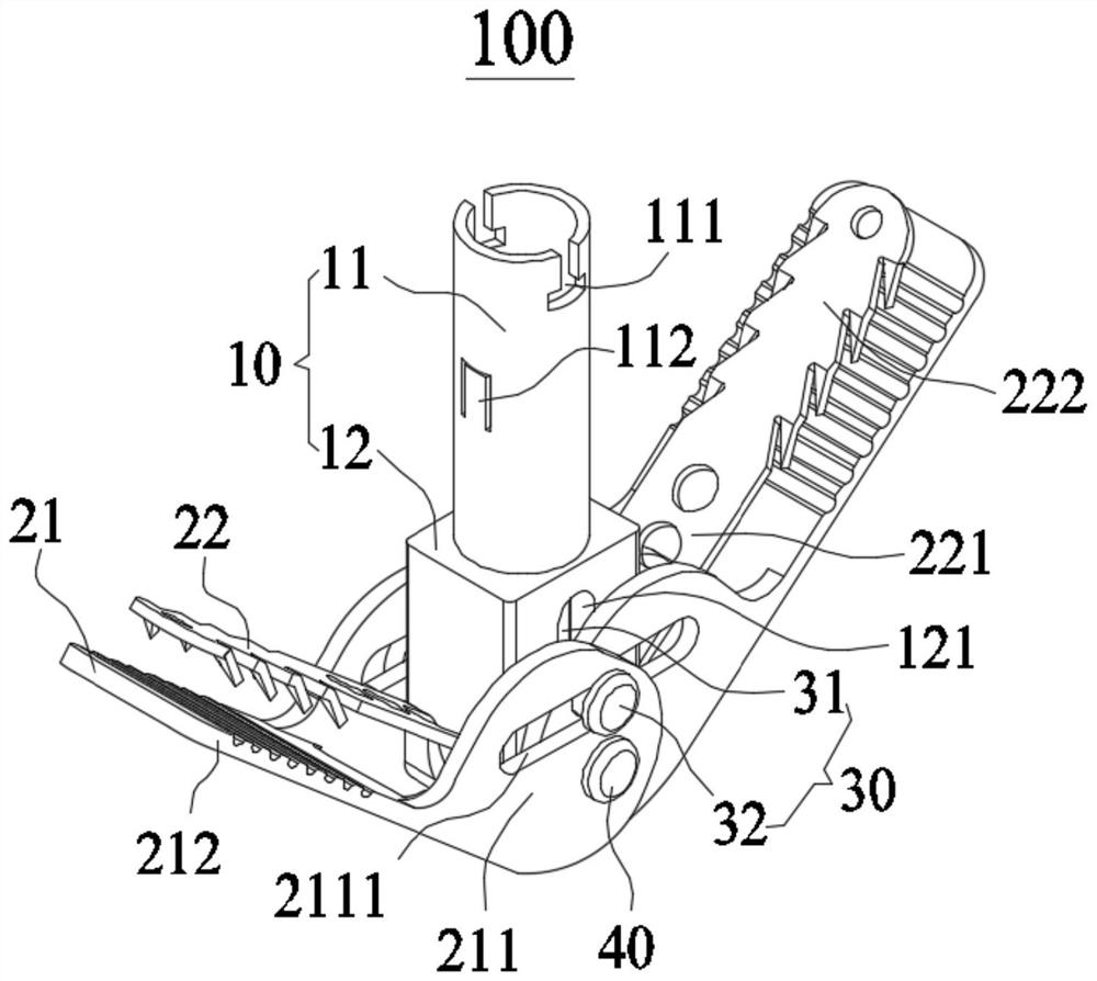
The invention provides an anti-slip valve clamping device and a valve clamping system. The valve clamping system comprises a pushing device and a valve clamping device. The valve clamping device comprises a base and at least two tong arms which are opened and closed relative to the base, each tong arm comprises a connecting end and a free end, the connecting ends of the at least two tong arms arerotationally connected with the base through the same rotating shaft, and the connecting ends of the at least two tong arms are partially staggered. According to the valve clamping device, the connecting ends of the at least two forceps arms are rotationally connected to the base through the same rotating shaft, and the connecting ends of the at least two forceps arms are partially staggered, so that the valve clamping device is small in overall size and light in weight, conveying is convenient, and the anti-slip performance is high.

Description

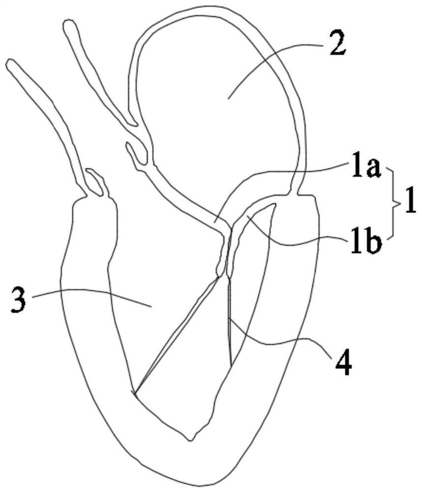
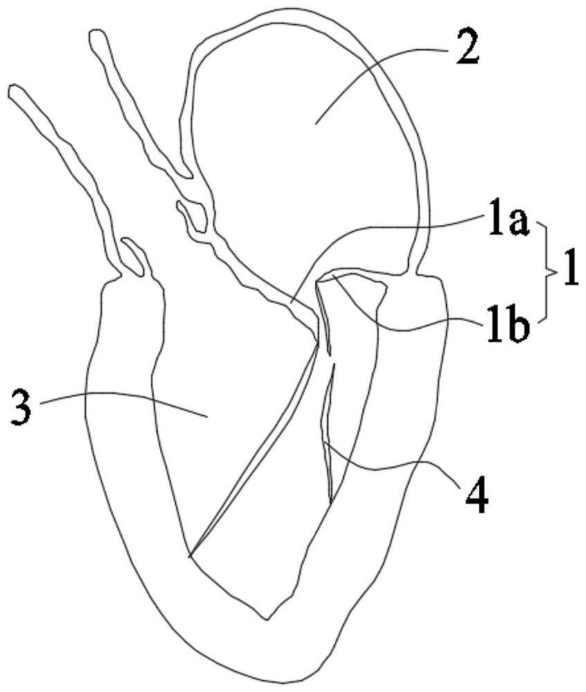
technical field [0001] The invention relates to the field of medical devices, in particular to an anti-slip valve clipping device and a valve clipping system. Background technique [0002] see figure 1 , the mitral valve 1 is a one-way valve located between the left atrium 2 and the left ventricle 3 of the heart. A normal and healthy mitral valve 1 can control blood flow from the left atrium 2 to the left ventricle 3 while preventing blood flow from the left ventricle 3 to the left atrium 2. The mitral valve 1 includes a pair of leaflets called an anterior leaflet 1a and a posterior leaflet 1b. The anterior lobe 1a and the posterior lobe 1b are fixed to the papillary muscle of the left ventricle 3 through the chordae 4 . Under normal circumstances, when the left ventricle 3 of the heart contracts, the edges of the anterior lobe 1a and the posterior lobe 1b are completely joined to prevent blood from flowing from the left ventricle 3 to the left atrium 2 . see figure 2 ...

Claims


Application Information

Patent Timeline
IPC IPC(8): A61F2/24
CPCA61F2/246A61F2/2466
Inventor 张庭超郑贤章张伟伟王泽涛
Owner HANGZHOU VALGEN MEDTECH CO LTD
Learn More