Supercharge Your Innovation With Domain-Expert AI Agents!

Bandage binding equipment

A technology for bandages and equipment, applied in the medical field, can solve the problems of low efficiency, slowness, inconvenience, and unfamiliarity with the work of tying bandages, and achieves the effect of simple structure and convenient use.

Inactive Publication Date: 2021-03-12
中山市康坦医疗设备科技有限公司
View PDF0 Cites 2 Cited by
  • Summary
  • Abstract
  • Description
  • Claims
  • Application Information

AI Technical Summary

Problems solved by technology

[0002] Existing patients usually need to apply medicine and then tie bandages after their hands and feet are injured. Due to the fact that there are often too many patients and insufficient medical staff during the peak hours of the hospital, the efficiency is low, because the injured people are inconvenient to move and the work of bandaging is difficult. If you are not familiar with it, you can’t tie the bandage on your own, and the delay in hemostasis will easily lead to deeper accidents, which is very inconvenient

Method used


Image

  • Bandage binding equipment
  • Bandage binding equipment
  • Bandage binding equipment

Examples


Embodiment Construction

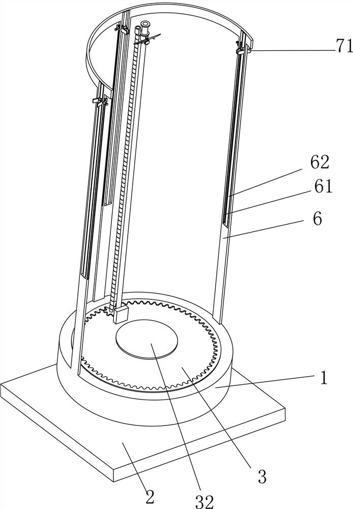
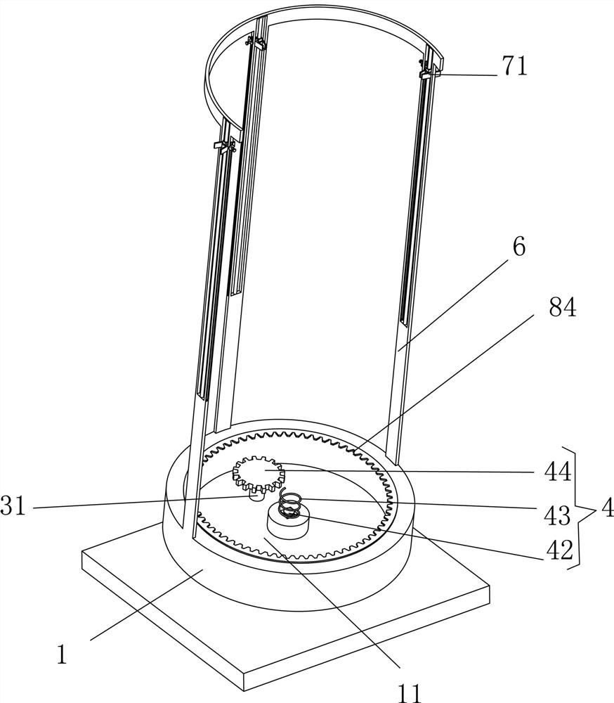
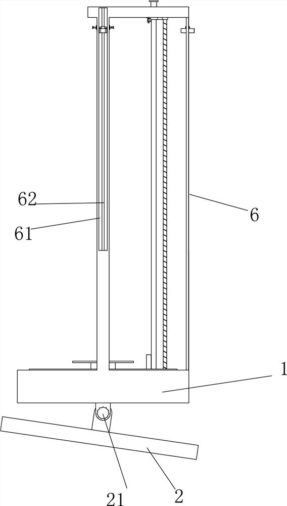
[0021] The present invention will be further described below in conjunction with accompanying drawing description and specific embodiment: Figures 1 to 7 The shown bandage device includes a box body 1, an inner cavity 11 is provided in the box body 1, and a movable bottom plate 2 is hinged at the bottom of the box body 1, and the bottom plate 2 and the box body A tightening head 21 is provided at the hinge between 1, a rotatable rotating plate 3 is provided on the inner cavity 11, a motor 31 is provided at the bottom of the inner cavity 11, and a rotating plate 3 is provided at the center of the inner cavity 11 The pressing plate 32 that can move up and down is provided in the inner cavity 11. When the pressing plate 32 is pressed down, the linkage mechanism 4 that can drive the motor 31 to rotate and rotate the rotating plate 3 is provided. A bandage can be placed above the box body 1. The rotating shaft 5 of the roll is provided with a plurality of vertical rods 6 on the up...


PUM


Abstract

The invention discloses bandage binding equipment, which comprises a box body, an inner cavity is formed in the box body, a movable bottom plate is hinged to the bottom of the box body, a tightening head is arranged at the hinged position between the bottom plate and the box body, a rotatable rotating plate is arranged on the inner cavity, and a motor is arranged at the bottom of the inner cavity.A pressing plate capable of moving up and down is arranged in the center of the rotating plate, a linkage mechanism capable of driving the motor to rotate and enabling the rotating plate to rotate when the pressing plate is pressed down is arranged in the inner cavity, a rotating shaft capable of containing bandage rolls is arranged above the box body, a plurality of vertical rods are arranged onthe upper wall of the box body, and long grooves are formed in the vertical rods. A stand column is fixed in the long groove, a clamping mechanism capable of moving up and down and clamping one end of a bandage is arranged on the stand column, and a moving mechanism capable of driving the bandage roll to rotate around the center of the rotating plate and enabling the rotating shaft to move downwards is arranged at the position, along the outer wall, of the rotating plate; and a shearing mechanism capable of shearing the bandage is arranged on one side of the rotating shaft.

Description

technical field [0001] The invention relates to the medical field, in particular to a bandage device. Background technique [0002] Existing patients usually need to apply medicine and then tie bandages after their hands and feet are injured. Due to the fact that there are often too many patients and insufficient medical staff during the peak hours of the hospital, the efficiency is low, because the injured people are inconvenient to move and the work of bandaging is difficult. If you are not familiar with it, you cannot tie a bandage on your own, and the delay in hemostasis will easily lead to deeper accidents, which is very inconvenient. [0003] Therefore, existing help bandage equipment needs further improvement. Contents of the invention [0004] Aiming at the defects in the above-mentioned prior art, the technical problem to be solved by the present invention is to make medical personnel and the wounded do not need to carry out the work of bandaging themselves. [...

Claims


Application Information

Patent Timeline
IPC IPC(8): A61F15/00
CPCA61F15/005
Inventor 王炳芝
Owner 中山市康坦医疗设备科技有限公司
Features
  • R&D
  • Intellectual Property
  • Life Sciences
  • Materials
  • Tech Scout
  • Unparalleled Data Quality
  • Higher Quality Content
  • 60% Fewer Hallucinations
Learn More