Jet flow range extending method based on composite flow synergy and device

A composite flow and jet technology, which can be applied in the direction of injection devices, liquid injection devices, etc., can solve problems such as the limitation of the range limit, and achieve the effect of promoting full mixing, wide practicability, and improving the range.

Active Publication Date: 2021-03-12
UNIV OF SCI & TECH OF CHINA
View PDF10 Cites 1 Cited by
  • Summary
  • Abstract
  • Description
  • Claims
  • Application Information

AI Technical Summary

Problems solved by technology

Most of the existing development ideas of long-distance injection technology focus on improving the power at the inlet end. For example, patent CN202010245877.2 and patent CN201020139897.3 use the high-speed air flow generated by the fan to increase the spray distance of the mist medium, and the range limit is limited by the power of the power device.
At present, there are few remote injection technologies developed from the perspective of reducing the resistance of the jet path

Method used


Image

  • Jet flow range extending method based on composite flow synergy and device
  • Jet flow range extending method based on composite flow synergy and device
  • Jet flow range extending method based on composite flow synergy and device

Examples


Embodiment 1

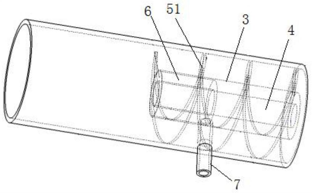
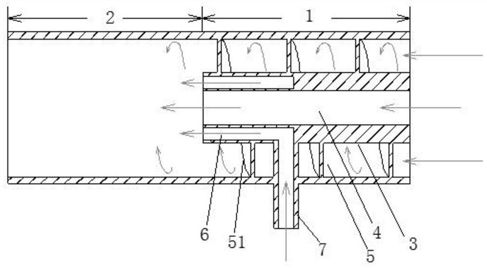
[0040] Please refer to Figure 1 to Figure 2 In this embodiment, the structure of the device for realizing the above-mentioned jet-fluid range-extending method based on composite flow coordination is set as follows:

[0041]A through cylindrical chamber is formed in the device as the injection channel of the effective medium. The front section of the injection channel is the inlet section 1, the rear section is the mixing section 2, and the front end of the inlet section 1 is the inlet port, which is used to feed high-speed Fluid, the rear end of the mixing section 2 is the outlet end; the entire section of the inlet section 1 is provided with a through partition pipe 3 in the middle along the axial direction, and the inner area of ​​the partition pipe 3 is used as an axial jet channel 4, and the outer wall and the inlet An annular area is formed between the inner walls of the section 1, and spiral guide vanes 51 are arranged axially to form a swirling flow channel 5, and an a...

Embodiment 2

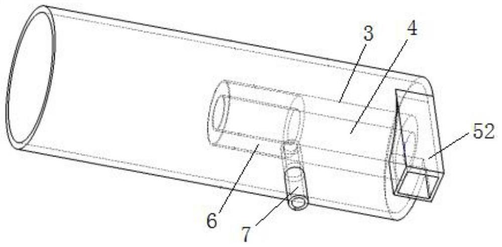
[0046] Please refer to Figure 3 to Figure 6 In this embodiment, the structure of the device for realizing the above-mentioned jet-fluid range-extending method based on composite flow coordination is set as follows:

[0047] A through cylindrical chamber is formed in the device as the injection channel of the effective medium, the front section of the injection channel is the inlet section 1, the rear section is the mixing section 2, and the rear end of the mixing section 2 is used as the outlet end; the inlet section 1 The entire section of the partition tube 3 is arranged in the middle along the axial direction, and the front nozzle of the partition tube 3 communicates with the outside; the inner area of ​​the partition tube 3 is used as the axial jet channel 4, and the front nozzle is used as the axial jet channel 4. Jet flow inlet; an annular area is formed between the outer wall of the partition pipe 3 and the inner wall of the inlet section 1, which communicates with the...


PUM


Abstract

The invention provides a jet flow range extending method based on composite flow synergy. The jet flow range extending method is characterized in that central axis high-speed jet flow linearly advancing along a central axis and peripheral rotational flow spirally advancing on the periphery of the central axis high-speed jet flow are formed correspondingly by utilizing high-speed fluid in a jet channel for an effective medium, the central axis high-speed jet flow and the peripheral rotational flow form a composite flow, the composite flow carries the effective medium introduced into the jet channel, a central low-pressure low-resistance area is formed by means of the centrifugal effect of the peripheral rotational flow, air resistance on an effective medium jet path is reduced, the jet speed of the effective medium is increased by means of boosting of the central axis high-speed jet flow, and remote jet of the effective medium is achieved. The invention provides two composite flow devices with different structural forms for realizing the method at the same time. According to the jet flow range extending method based on composite flow synergy, the idea of reducing the resistance on the effective medium jet path by utilizing the peripheral rotational flow is brand new in the field, and the range of the effective medium is greatly improved under the same power condition.

Description

technical field [0001] The invention relates to the field of public safety, more specifically to a method and device for jet range extension based on composite flow coordination. Background technique [0002] Realizing the remote spraying of effective media has great significance in enhancing the effect, expanding the area of ​​action, and reducing the cost of use in the fields of safety, hygiene, agriculture, and environmental protection. Most of the development ideas of the existing remote injection technology focus on improving the power at the inlet end, such as patent CN202010245877.2 and patent CN201020139897.3, which use the high-speed air flow generated by the fan to increase the spray distance of the mist medium, and the range limit is limited by the power of the power device . At present, there are few remote injection technologies developed from the perspective of reducing the resistance of the jet path. Contents of the invention [0003] Aiming at the deficie...

Claims


Application Information

Patent Timeline
Patent Type & Authority Applications(China)
IPC IPC(8): B05B7/04B05B7/14
CPCB05B7/0416B05B7/0408B05B7/1436
Inventor 王喜世孙华中朱小龙
Owner UNIV OF SCI & TECH OF CHINA
Why Eureka
Try Eureka