
Metal plate punching machine tool with automatic fastening and clamping function

A technology for sheet metal and stamping machine tools, which is applied in metal processing equipment, manufacturing tools, feeding devices, etc., and can solve problems such as different specifications, sheet damage, and stamping equipment that cannot be bent.

Active Publication Date: 2021-03-12
东莞市雄联五金制品有限公司
View PDF9 Cites 0 Cited by
  • Summary
  • Abstract
  • Description
  • Claims
  • Application Information

AI Technical Summary

Problems solved by technology

[0002] The existing stamping equipment has many shortcomings. First, the stamping equipment cannot realize bending in the actual use process, and because the corresponding dies for stamping and bending are different, it is impossible to integrate the two in the existing equipment. Work in different ways in one device, and during the bending process of the corresponding sheet, the sheet will be lifted accordingly, and the bent sheet is long or short, and the specifications are different. During the bending process of small plates, the plates will be lifted directly, but when some larger plates are bent, partial lifting will occur, and the partial lifting will cause deformation of the plates , there is no good technical solution to overcome this problem in the existing technology, which has caused potential damage caused by local deformation of the plate. The above shortcomings have greatly reduced the actual working efficiency and reliability of the equipment.

Method used


Image

  • Metal plate punching machine tool with automatic fastening and clamping function
  • Metal plate punching machine tool with automatic fastening and clamping function

Examples


Embodiment Construction

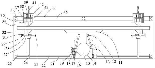
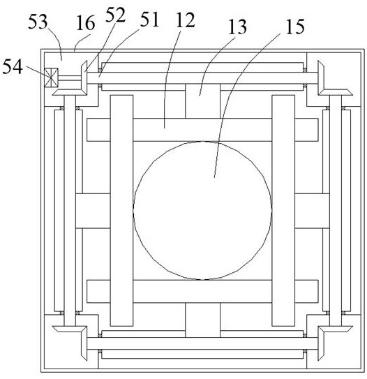
[0018] Such as Figure 1-Figure 2 As shown, the present invention is described in detail. For the convenience of description, the orientations mentioned below are now stipulated as follows: figure 1 The up, down, left, right, front and back directions of the projection relationship are consistent. A sheet metal stamping machine tool with automatic fastening and clamping function of the present invention includes an intermediate connecting rod 34, and the intermediate connecting rod 34 is provided with a penetrating buffer inner cavity 21. The top of the intermediate connecting rod 34 is provided with a penetrating moving cavity 44, the moving cavity 44 is symmetrically arranged, and the moving cavity 44 and the buffer inner cavity 21 are provided with a cutting and bending device capable of switching between bending and cutting modes A bottom seat 16 is provided for rotation in the middle connecting rod 34, a gear ring 18 is provided on the top of the middle connecting rod 34,...


PUM


Abstract

The invention discloses a metal plate punching machine tool with an automatic fastening and clamping function. The metal plate punching machine tool with the automatic fastening and clamping functioncomprises a middle connecting rod, a through buffering inner cavity is formed in the middle connecting rod, through moving cavities are formed in the top of the middle connecting rod, the moving cavities are symmetrically arranged, Cutting-off and bending devices capable of being switched between a bending mode and a cutting-off mode are arranged in the moving cavities and the buffering inner cavity, a bottom seat is rotationally arranged in the middle connecting rod, a gear ring is arranged at the top of the middle connecting rod, an internal connecting motor is arranged in the bottom seat, and a meshing gear is arranged on one side of the internal connecting motor in a power connection mode. According to the equipment, a plate can be placed in the equipment, the plate can be switched back and forth between punching and cutting, excessive deformation of the plate can be prevented, and a placing platform can incline and tilt after the plate is punched.

Description

technical field [0001] The invention relates to the technical field of stamping equipment, in particular to a sheet metal stamping machine tool with automatic fastening and clamping functions. Background technique [0002] The existing stamping equipment has many shortcomings. First, the stamping equipment cannot realize bending in the actual use process, and because the corresponding dies for stamping and bending are different, it is impossible to integrate the two in the existing equipment. Work in different ways in one device, and during the bending process of the corresponding sheet, the sheet will be lifted accordingly, and the bent sheet is long or short, and the specifications are different. During the bending process of small plates, the plates will be lifted directly, but when some larger plates are bent, partial lifting will occur, and the partial lifting will cause deformation of the plates However, there is no good technical solution to overcome this problem in ...

Claims


Application Information

Patent Timeline
IPC IPC(8): B21D5/02B21D43/00B21D28/02
CPCB21D5/002B21D5/02B21D28/02
Inventor 不公告发明人
Owner 东莞市雄联五金制品有限公司
Learn More