Rolling forming machine
A molding machine and rolling technology, applied in storage devices, metal processing equipment, feeding devices, etc., can solve problems such as low efficiency and achieve the effect of improving adjustment efficiency
- Summary
- Abstract
- Description
- Claims
- Application Information
AI Technical Summary
Problems solved by technology
Method used
Image

Examples
Embodiment 1
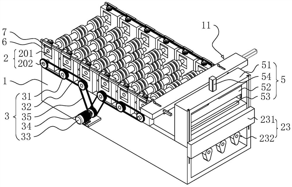
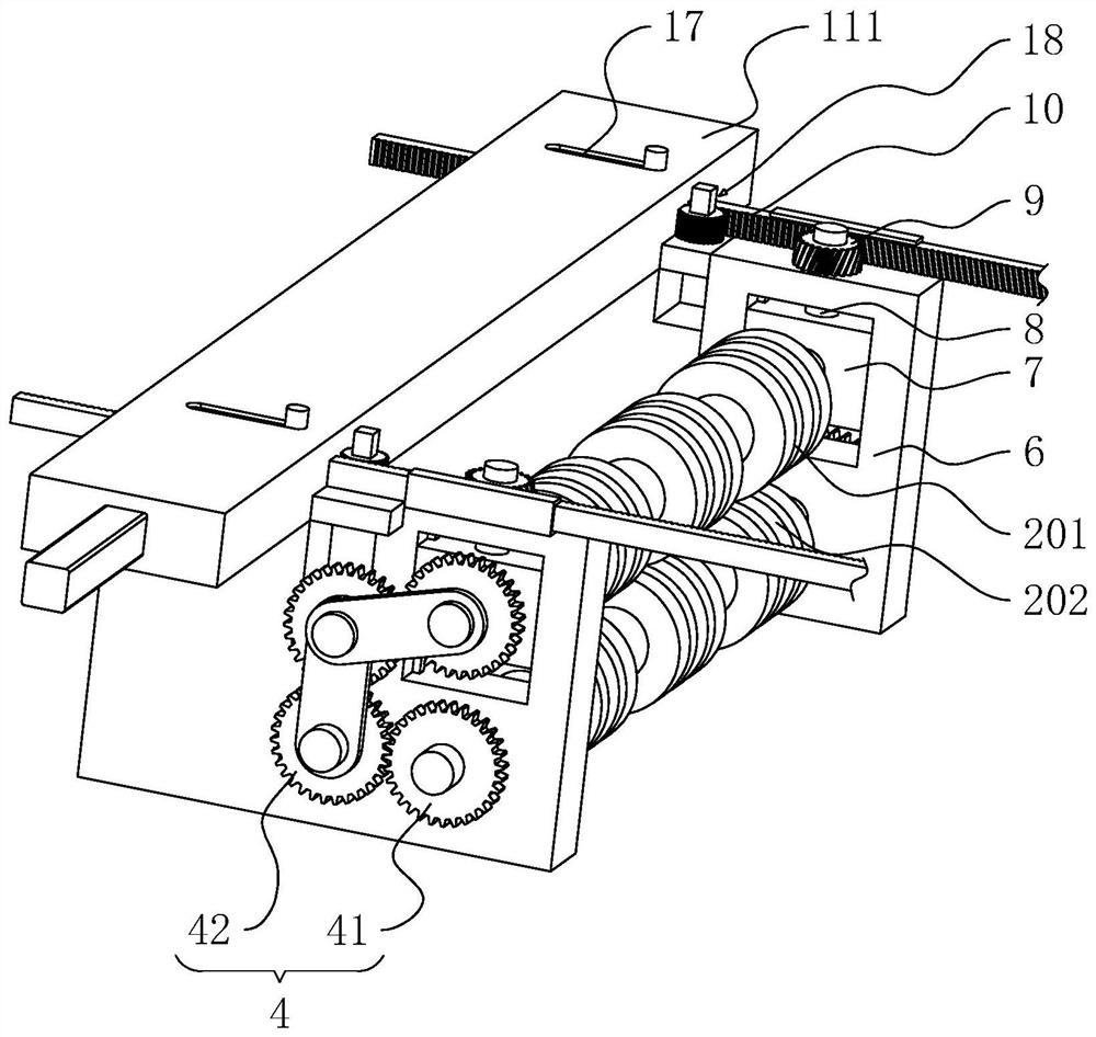
[0039] Refer figure 1 , figure 2 As shown, the roller compression molding machine includes a frame 1, a plurality of road molding units 2, a driving device 3, a transmission assembly 4, and a shear apparatus 5, each of which is arranged to the rack 1 along the direction of material traveling. The device 5 is mounted on the discharge end of the rack 1 for cropping the material according to production specifications. Each of the molding units 2 includes an upper roller 201 and a lower roll 202 disposed in parallel, and the driving device 3 is disposed on the side of the frame 1 for driving each down-roll 202, and each of the transmission assemblies 4 is mounted to the lower roller 202 away from the drive. One end of the device 3 is rotated by driving the upper roll 201. A number of pairs of mount 6 is fixed to the mounting of the upper roll 201 and the lower roller 202, each lower roller 202 is rotated to the mounting seat 6, and the mount 6 is lift the slip-slip seat. 7, each of ...
Embodiment 2
[0049] Refer Figure 6 , Figure 7 As shown, the present embodiment differs from the first embodiment in that the synchronous drive assembly 11 includes a second box body 24, a second drive source 25, an active wheel 26, and a driven wheel 27, and the second box body 24 is mounted to the rack. 1 and located between the two first racks 10, the second box 24 is opened to the seventh slide 28 for slipping of two first racks 10, and the second drive source 25 is mounted to the second box. On the upper side, the active wheel 26 is disposed on the output of the second driving source 25, and the driven wheel 27 is provided with two groups, each of which is rotated in the second case 24, and the transmission ratio is 1: 1. The two sets of driven wheels 27 are located on one side of the drive wheel 26 near the first rack 10, and the driven wheels 27 on one side of the two sets of driven wheels 26 are respectively adjusted to the corresponding first teeth. The strip 10 meshes, wherein a set ...
PUM
 Abstract
Description
Claims
Application Information
 - R&D Engineer
- R&D Manager
- IP Professional
- Industry Leading Data Capabilities
- Powerful AI technology
- Patent DNA Extraction
Browse by: Latest US Patents, China's latest patents, Technical Efficacy Thesaurus, Application Domain, Technology Topic.
© 2024 PatSnap. All rights reserved.Legal|Privacy policy|Modern Slavery Act Transparency Statement|Sitemap