Motor belt pulley pulling device

A technology of motor pulleys and telescopic devices, which is applied in the direction of hand-held tools and manufacturing tools, can solve the problems of affecting disassembly, failure of pulling pulleys, difficult disassembly of pulleys, etc., and achieves the effects of preventing deformation, strong adaptability, and high structural strength

Pending Publication Date: 2021-03-12
高代顺
View PDF1 Cites 0 Cited by
  • Summary
  • Abstract
  • Description
  • Claims
  • Application Information

AI Technical Summary

Problems solved by technology

In the patent document with the application number 201620786259.8, two kinds of motor pulley removal tools are disclosed. The removal tools can safely and quickly disassemble motor pulleys with different diameters on the well of the oil inserter. The stable condition will affect disassembly; when the force is exerted by the jacking screw, the clamp responsible for holding the pulley is easily deformed and the pulley will fall off, resulting in failure of the pulling pulley; in addition, the current disassembly device has a small scope of application for different sizes of motor pulleys. Larger pulleys are difficult to disassemble by jacking screw rods, and it is difficult for general tools to catch the pulleys of large motors. The different specifications of the pulley grooves of the motor pulleys also need to be fixed with different clamping structures.

Method used


Image

  • Motor belt pulley pulling device
  • Motor belt pulley pulling device
  • Motor belt pulley pulling device

Examples


no. 1 example

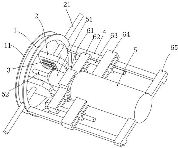
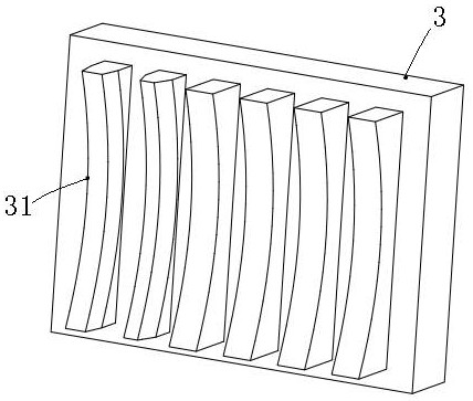
[0023] Motor pulley pulley, such as figure 1 with figure 2 As shown, at least two of the cuvers 2, including the circular array distribution, in particular, two junction clamp 2, which are both embedded in the inner side of the cuvers 2, and A bump 31 is provided with a pulley block 3; a splint rod 21 is mounted in the outer side of the pulleys 2, and the central pendulum rod 21 is in a fixed frame. 1 and with the fixture 1 thread;

[0024] A socket 52 is provided at the position between the cupping clamp 2, and the top rod 52 is located on the centerline of the circular array, and the position of the end rod 52 is secured to a telescopic device 5. One end of the top rod 52 is fixedly coupled to the telescopic rod 51 of the telescopic device 5 and is disposed with the telescoping rod 51; the first tilt rod 61 is provided, one end of the first lever 61. Another end of the first tie rod 61 stops on a fixed arrangement tie rod assembly, the first tilt rod 61 relays a radial sliding...

no. 2 example

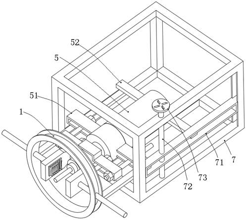
[0031] Other technical features are the same as in the first embodiment, combined image 3 As shown, the telescopic device 5 lifted down, and specifically, in the bracket 7, a beam 71 is provided, and both ends of the beam 71 are slidably mounted on the bracket 7, in the stent. 7 Turn the vertical rod 72, the middle portion of the filament 72 penetrates through the beam 71 and threads with the beam 71, and the hand wheel 73 is fixed at the top end of the rod 72, and the telescopic The device 5 is fixed to the beam 71. The first sliding rail 64 and the connecting plate 65 are fixed to the cylinder of the telescopic device 5, the first sliding rail 64, and the connecting plate 65 located at both ends of the cylinder of the telescopic device and The beam 71 is fixedly connected.

no. 3 example

[0033] Other technical features are the same as in the first embodiment or the second embodiment, combined Figure 4 with Figure 5 As shown, the tie rod assembly includes a plurality of first sliding rails 64 corresponding to the first lever 61, the first lever 61 recesses and the first sliding rail 64 corresponding to it. The first sliding rail 64 slides together, and the first sliding rail 64 is fixedly coupled to the telescopic device.

[0034] The working principle of the present invention is to rotate the rod by rotating the hand wheel, thereby allowing the beam to drive the telescopic device, put the equivalent height of the belt wheel into the cuvet splint, turn the splint splitter to close each other, and make the hug The wheelcarca card is connected to the pulley, the telescopic device extends out the telescopic rod, the telescopic rod drives the top rod and holds the rotation shaft of the center position of the pulley, and the rotor is jealous out of the pulley, thereby ...


PUM


Abstract

The invention discloses a motor belt pulley pulling device. The device comprises at least two pulley pulling clamping plates which are distributed in the manner of a circular array, wherein pulley holding clamping blocks are embedded in the inner sides of the pulley pulling clamping plates. Clamping plate screw rods are rotationally mounted on the outer sides of the pulley pulling clamping plates,and the middle parts of the clamping plate screw rods are arranged on a fixing frame in a penetrating manner and are in threaded fit with the fixing frame. An ejector rod is arranged between the pulley pulling clamping plates, and one end of the ejector rod is fixedly connected with a telescopic rod of a telescopic device and is coaxial with the telescopic rod. A first pull rod is arranged on each pulley pulling clamping plate, one end of each first pull rod is fixedly connected with the corresponding pulley pulling clamping plate, the other end of each first pull rod is stopped on a fixedly-arranged pull rod assembly, and the first pull rods are in sliding fit in the radial direction of the circular array. A belt pulley is clamped by the pulley pulling clamping plates, the pulley holdingclamping blocks are connected with the belt pulley in a clamping manner, a rotating shaft is ejected out by the ejector rod so that the belt pulley can be separated from the rotating shaft, meanwhile, the first pull rods pull the pulley pulling clamping plates, and it is avoided that the pulley pulling clamping plates deform and cannot clamp the belt pulley. The motor belt pulley pulling device is high in structural strength and adaptability.

Description

Technical field [0001] The present invention relates to the field of motor pulley removal technology, and more particularly to a motor pulley pulley. Background technique [0002] Motor (English: Electric Machinery, commonly known as "motor"> refers to an electromagnetic device that implements electrical energy conversion or transmission in accordance with electromagnetic induction. In the circuit, the alphabetic standard is used in the circuit. Its main role is to generate drive torque as a power source with a tunnel or a variety of mechanical. The generator is expressed in the circuit. Its main work layer is to utilize electrical energy conversion to mechanical energy. [0003] For various reasons, the pulley of the motor is required to replace or simply disassemble the motor. When replacing the motor belt, the original motor belt must be removed. Earl, the technicians use the slurry iron and hammer to strike the motor pulley, so that the motor pulley is loose and motor bear...

Claims


Application Information

Patent Timeline
Patent Type & Authority Applications(China)
IPC IPC(8): B25B27/02
CPCB25B27/02
Inventor 高代顺
Owner 高代顺
Why Eureka
Try Eureka