Supercharge Your Innovation With Domain-Expert AI Agents!

Multi-degree-of-freedom mechanical arm

A technology of manipulators and degrees of freedom, which is applied in the direction of manipulators, program-controlled manipulators, chucks, etc., and can solve problems such as falling objects

Inactive Publication Date: 2021-03-12
巩春涛
View PDF13 Cites 0 Cited by
  • Summary
  • Abstract
  • Description
  • Claims
  • Application Information

AI Technical Summary

Problems solved by technology

However, the existing manipulator cannot assist in fixing the items when grabbing them, so that the items may fall when the items are carried.

Method used


Image

  • Multi-degree-of-freedom mechanical arm
  • Multi-degree-of-freedom mechanical arm
  • Multi-degree-of-freedom mechanical arm

Examples


specific Embodiment approach 1

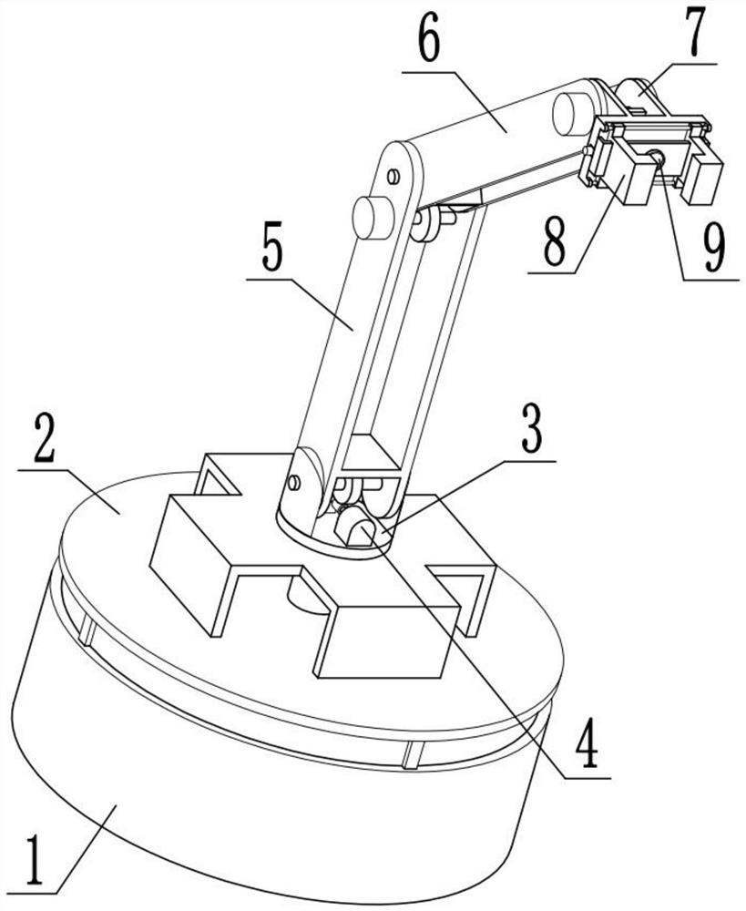
[0033] Combine below Figure 1-11This embodiment is described. The present invention relates to the technical field of manipulator equipment, more specifically, a multi-degree-of-freedom manipulator, including a load-bearing connection seat member 1, a lifting support member 2, a rotating connection seat member 3, an angle adjustment device 4, and a first-stage The power arm device 5, the secondary power arm device 6, the hinged connection seat member 7, the extrusion fixing device 8 and the vacuum adsorption device 9, the power arm can be adjusted through the transmission connection between the worm gear 5-3 and the worm 4-1 by using the motor II4-3 For the angle of I5-1, the angle of the power arm II6-1 can be adjusted by using the motor III5-6 through the gear II6-3 meshing with the gear I5-5, and the angle of the connecting seat 7-1 can be adjusted by starting the motor IV6-4. Two motors V7-5 can drive two extruding convex plates 8-2 to clamp and fix the article, and the s...

specific Embodiment approach 2

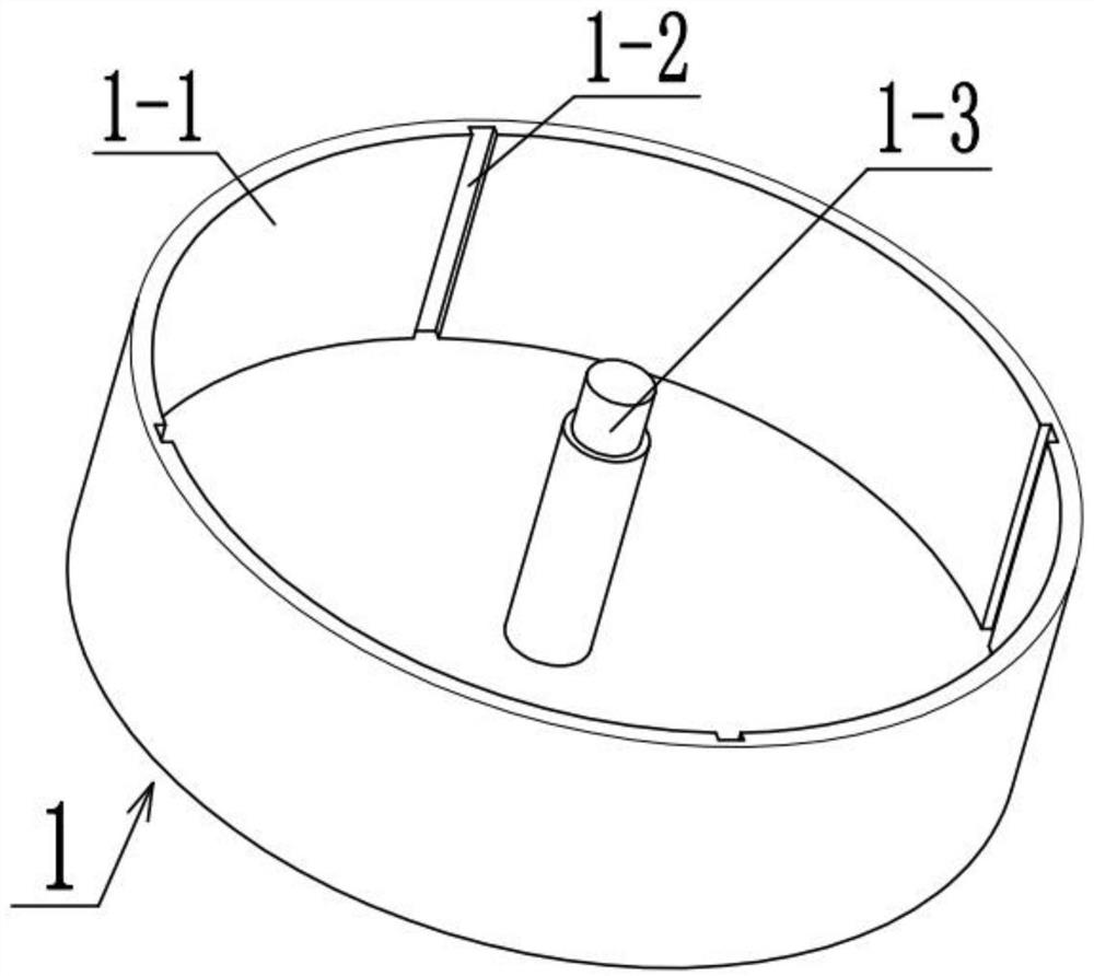
[0036] Combine below Figure 1-11 Describe this embodiment. This embodiment will further explain Embodiment 1. The load-bearing connection seat member 1 includes a connecting sliding cavity 1-1, a limit keyway 1-2, and an elevating and shrinking rod I1-3. The connecting sliding cavity 1-1 To play the role of load-bearing connection, four limit key grooves 1-2 are evenly arranged in the circumferential direction of the connecting sliding chamber 1-1, and the four limit key grooves 1-2 can provide sliding space for the lifting sliding column 2-1 and It limits the position, so that the lifting sliding column 2-1 can only slide up and down, and the connecting sliding chamber 1-1 is fixedly connected with the lifting rod I1-3, and the lifting rod I1-3 can be used to drive the bearing circular plate 2-2 to carry out Moving up and down.

specific Embodiment approach 3

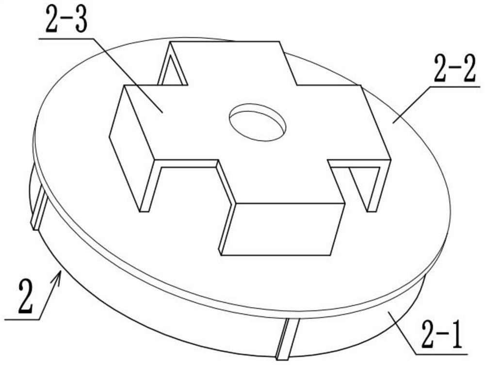
[0038] Combine below Figure 1-11 Describe this embodiment, this embodiment will further explain the second embodiment, the lifting support member 2 includes a lifting sliding column 2-1, a bearing circular plate 2-2 and a bearing seat I2-3, and the lifting sliding column 2-1 It plays the role of load-bearing connection. When the lifting sliding column 2-1 is slidably connected with the four limit keyways 1-2, the lifting sliding column 2-1 is limited, and the upper part of the lifting sliding column 2-1 is fixedly connected with a bearing circle. Plate 2-2, the load-bearing circular plate 2-2 plays the role of load-bearing connection, the lifting rod 1-3 is fixedly connected with the load-bearing circular plate 2-2, and the top of the load-bearing circular plate 2-2 is fixedly connected with the bearing seat I2-3 , The bearing seat I2-3 can provide a space for the adapter shaft 3-3 to rotate.


PUM


Abstract

The invention relates to the technical field of mechanical arm equipment, in particular to a multi-degree-of-freedom mechanical arm. The multi-degree-of-freedom mechanical arm comprises a bearing connecting base component, a lifting supporting component, a rotating connecting base component, an angle adjusting device, a first-stage power arm device, a second-stage power arm device, a hinge connecting base component, an extrusion fixing device and a vacuum adsorption device, the lifting supporting component is connected into the bearing connecting base component in a sliding mode, the rotatingconnecting base component is connected to the lifting supporting component, the angle adjusting device is fixedly connected to the rotating connecting base component, the first-stage power arm deviceis connected to the rotating connecting base component in a rotating mode and is in engaged transmission connection with the angle adjusting device, the second-stage power arm device is connected to the upper portion of the first-stage power arm device in a rotating mode, and the hinge connecting base component is connected to the second-stage power arm device in a rotating mode. According to themulti-degree-of-freedom mechanical arm, articles can be grabbed, the grabbed articles can further be fixed in an auxiliary mode, and the phenomenon that the articles fall off in the transportation process can be avoided.

Description

technical field [0001] The invention relates to the technical field of manipulator equipment, in particular to a multi-degree-of-freedom manipulator. Background technique [0002] An automatic operating device that can imitate certain movement functions of the human hand and arm to grasp, carry objects or operate tools according to a fixed program. The manipulator is the earliest industrial robot and the first modern robot. It can replace the heavy labor of people to realize the mechanization and automation of production, and can operate in harmful environments to protect personal safety. Therefore, it is widely used in machinery manufacturing, metallurgy, Electronics, light industry and atomic energy and other departments, with the development of network technology, the problem of networked operation of manipulators is also the direction of future development. Industrial robot is a kind of high-tech automatic production equipment developed in recent decades. Industrial ma...

Claims


Application Information

Patent Timeline
Patent Type & Authority Applications(China)
IPC IPC(8): B25J15/00B25J15/02B25J15/06B25J9/00B25J9/04B25J19/00
CPCB25J9/0009B25J9/04B25J15/0066B25J15/0253B25J15/0616B25J19/00
Inventor 巩春涛
Owner 巩春涛
Features
  • R&D
  • Intellectual Property
  • Life Sciences
  • Materials
  • Tech Scout
  • Unparalleled Data Quality
  • Higher Quality Content
  • 60% Fewer Hallucinations
Learn More