Ceramic injection machine convenient for controlling feeding amount

A technology of injection machine and control mechanism, applied in the field of ceramic production, can solve the problems of pipeline blockage, slurry condensation, unstable temperature control, etc.

Inactive Publication Date: 2021-03-12
罗运林
View PDF0 Cites 0 Cited by
  • Summary
  • Abstract
  • Description
  • Claims
  • Application Information

AI Technical Summary

Problems solved by technology

[0005] The invention provides a ceramic injection machine which is convenient to control the feeding amount, and solves the problem that the slurry will condense on the inner side of the pipeline due to too low temperature due to unstable temperature control during the feeding process, resulting in pipeline blockage on the inner side of the pipeline. Moreover, the existing injection machine cannot be controlled according to the required dosage during injection, resulting in uneven feeding of the slurry input into the mold, which causes the problem of excessive slurry usage

Method used


Image

  • Ceramic injection machine convenient for controlling feeding amount
  • Ceramic injection machine convenient for controlling feeding amount
  • Ceramic injection machine convenient for controlling feeding amount

Examples


Embodiment Construction

[0019] The present invention will be further described below in conjunction with the accompanying drawings and embodiments.

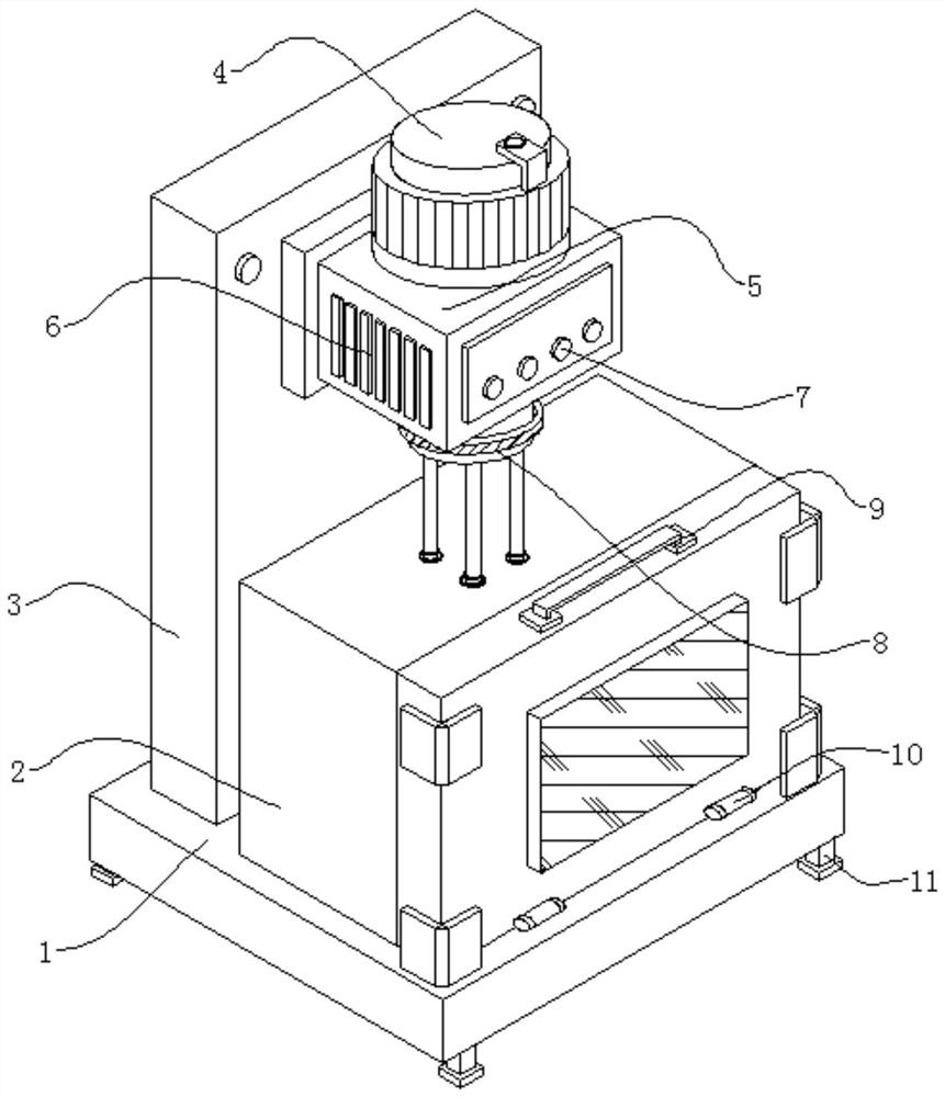
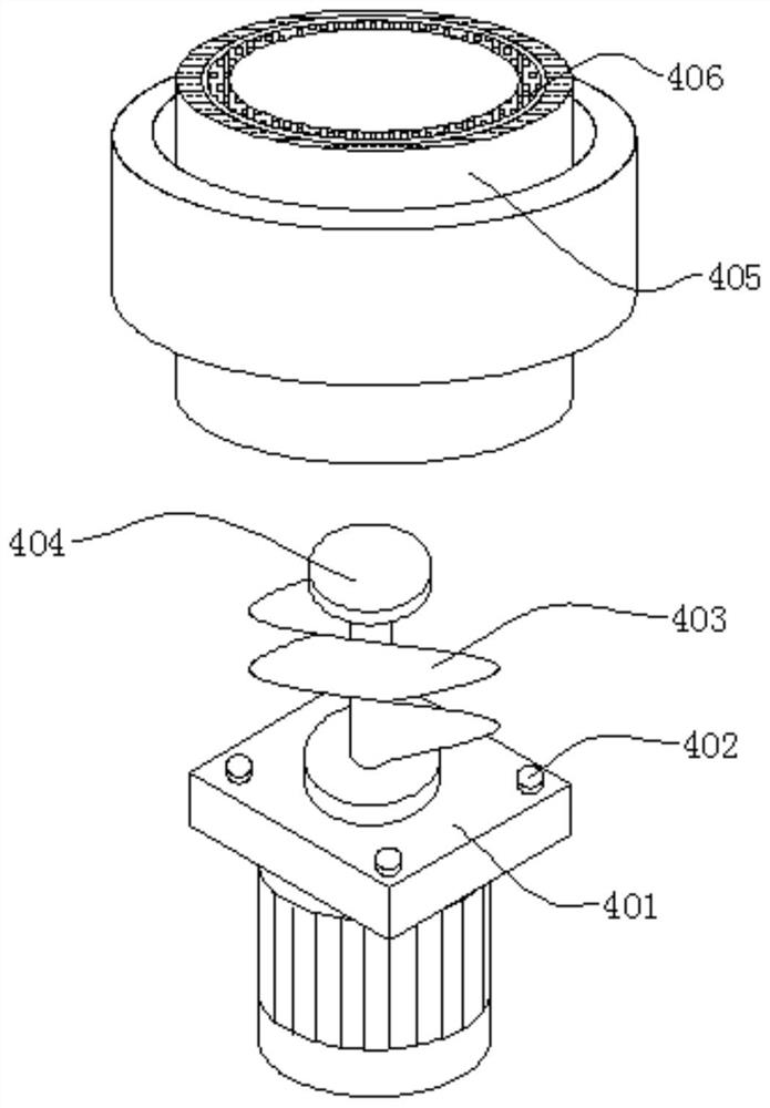
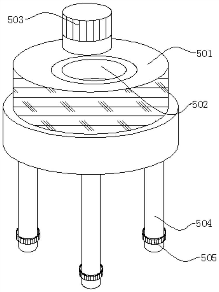
[0020] Please refer to figure 1 , figure 2 and image 3 ,in, figure 1 A structural schematic diagram of a preferred embodiment of a ceramic injection machine that is convenient for controlling the feeding amount provided by the present invention; figure 2 for figure 1 The structural schematic diagram of the overall disassembly of the feeding mechanism shown; image 3 for figure 1 The schematic diagram of the overall internal structure of the control device shown. A ceramic injection machine that is convenient for controlling the feeding amount, including a base 1, the upper end of the base 1 is fixedly installed with a molding box 2, the upper end of the base 1 is fixedly connected with a connecting plate 3, and the external connection of the connecting plate 3 is fixedly connected with a control mechanism 5, the control mechanism The upper end...


PUM


Abstract

The invention provides a ceramic injection machine convenient for controlling feeding amount. The ceramic injection machine convenient for controlling feeding amount comprises a base, a forming box isfixedly installed at the upper end of the base, a connecting plate is fixedly connected to the upper end of the base, and a control mechanism is fixedly connected to the outer portion of the connecting plate. According to the ceramic injection machine convenient for controlling feeding amount, first, material filling is carried out through a feeding mechanism at the upper end of the control mechanism, a cover plate at the upper end of the feeding mechanism is opened, then slurry is poured into the feeding mechanism to be stirred and heated, then the slurry is conveyed into the control mechanism, the use amount required by slurry injection inside material conveying pipes is controlled by a control panel outside the control mechanism, and then the slurry flows into a material conveying discalong with the control mechanism and is finally conveyed into a mold in a molding box for injection molding work. With the design, for the injection machine, the amount of the slurry needed to be injected in the mold can be effectively controlled, so that the quantitative injection effect of the injection machine is realized.

Description

technical field [0001] The invention relates to the field of ceramic production, in particular to a ceramic injection machine which is convenient for controlling the feeding amount. Background technique [0002] Injection machine (also known as injection molding machine) is the main molding equipment for making thermoplastic or thermosetting materials into plastic products of various shapes using plastic molding molds. Injection molding is realized through injection molding machines and molds. [0003] However, the existing ceramic injection machine, which is convenient for controlling the feeding amount, has a single design. In the ordinary injection machine, the temperature control is unstable during the feeding process. The problem of pipeline blockage, and the existing injection machine cannot be controlled according to the required amount during injection, resulting in uneven delivery of the slurry input into the mold, resulting in excessive slurry consumption and waste...

Claims


Application Information

Patent Timeline
IPC IPC(8): B28B1/26B28B13/02B28B17/00B28C1/22
CPCB28B1/26B28B13/0235B28B17/00B28B17/0081B28C1/227
Inventor 罗运林
Owner 罗运林
Why Eureka
Try Eureka