


Quick Research
Generate reliable direction feasibility study reports for your R&D in just a few steps.

Technical Q&A
Discover and master advanced knowledge NOW. Basics, ideas, possibilities, all at once.

Find Solutions
As an expert in R&D theories, this can generate solutions to your technical problems instantly.

Evaluate Feasibility
Analyze your overall solution with one click, know your potential R&D risks in advance.

Monitor Landscape
Get weekly tech updates, stay abreast of the latest tech innovations and key insights.
Paper box laminating and feeding equipment of laminating machine
A technology of feeding equipment and laminating machine, which is applied in the direction of papermaking, paper/cardboard containers, container manufacturing machinery, etc., and can solve the problems of film wrinkles and difficulty in unfolding
- Summary
- Abstract
- Description
- Claims
- Application Information
AI Technical Summary
Problems solved by technology
Method used
Image

Examples
Embodiment 1
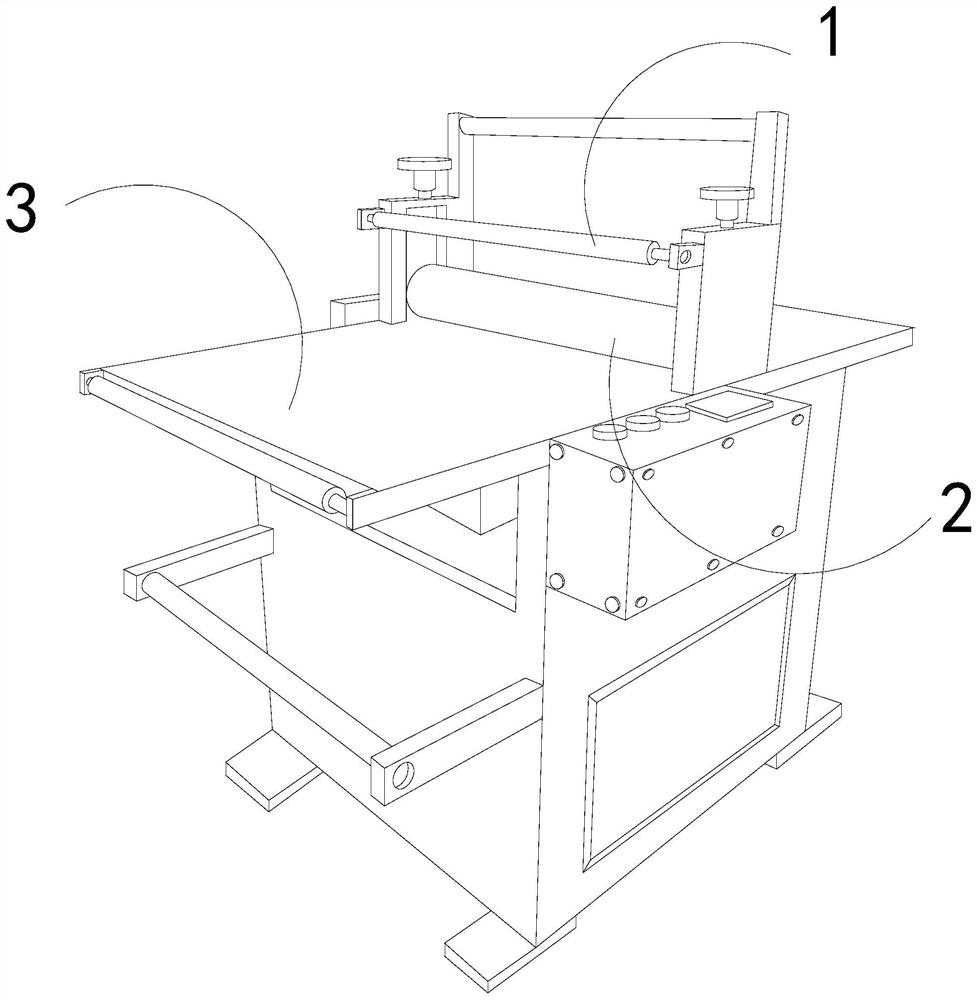
[0026] For example figure 1 -example Figure 5 Shown:
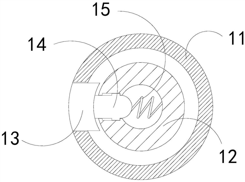
[0027] The invention provides a carton film feeding device for a laminating machine, the structure of which includes a feeding roller 1, a film collecting tube 2, and a machine body 3. The film collecting tube 2 is connected to the machine body 3, and the feeding roller 1 is connected to the machine body. The upper end of 3 is movable and engaged; the feeding roller 1 includes an outer ring 11, an inner ring 12, a front extension plate 13, a transition block 14, and a booster bar 15, and the inner ring 12 and the outer ring 11 are an integrated structure , the front extension plate 13 is embedded and fixed on the left side of the transition block 14, the transition block 14 is movably engaged with the inner ring 12, and the booster bar 15 is installed on the inner side of the transition block 14 and the inner ring 12 Location.
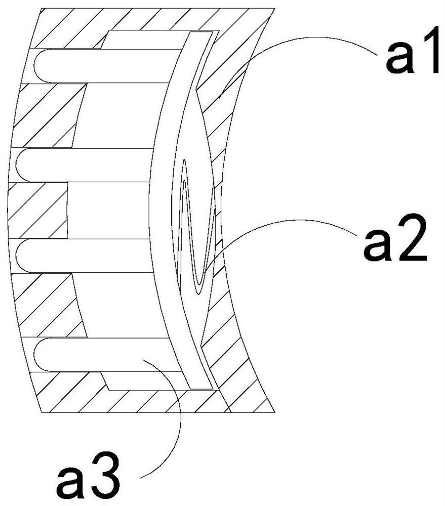
[0028] Wherein, the front extension plate 13 includes an outer frame a1, an outer push bar ...
Embodiment 2
[0034] For example Figure 6 -example Figure 8 Shown:
[0035] Wherein, the position fixing plate b1 includes a position fixing plate b11, a resilient piece b12, a blocking roller b13, and a retracting plate b14. The blocking roller b13 is engaged with the internal movement of the retracting plate b14. The compound elastic piece b12 is connected with the positioning plate b11, through the thrust generated by the object on the retracting plate b14, the retracting plate b14 can be shrunk inward, so that the retracting plate b14 can connect the retracting plate b14 and the positioning plate b11 Moisture squeezes out.
[0036] Wherein, the blocking roller b13 includes an outer expansion plate c1, a middle plate c2, and an elastic ring c3. The outer expansion plate c1 is movably engaged with the middle plate c2 through the elastic ring c3. The outer expansion plate c1 is provided with two one, and evenly distributed symmetrically at the upper and lower ends of the middle plate ...
PUM
 Abstract
Description
Claims
Application Information
 - R&D Engineer
- R&D Manager
- IP Professional
- Industry Leading Data Capabilities
- Powerful AI technology
- Patent DNA Extraction
Browse by: Latest US Patents, China's latest patents, Technical Efficacy Thesaurus, Application Domain, Technology Topic, Popular Technical Reports.
© 2024 PatSnap. All rights reserved.Legal|Privacy policy|Modern Slavery Act Transparency Statement|Sitemap|About US| Contact US: help@patsnap.com