Sewage treatment device with automatic deslagging function
A sewage treatment device, automatic slag discharge technology, applied in water/sewage treatment, water/sewage multi-stage treatment, water/sewage treatment equipment, etc. interruptions, etc.
- Summary
- Abstract
- Description
- Claims
- Application Information
AI Technical Summary
Problems solved by technology
Method used
Image
Examples
Embodiment 1
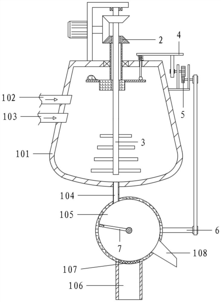
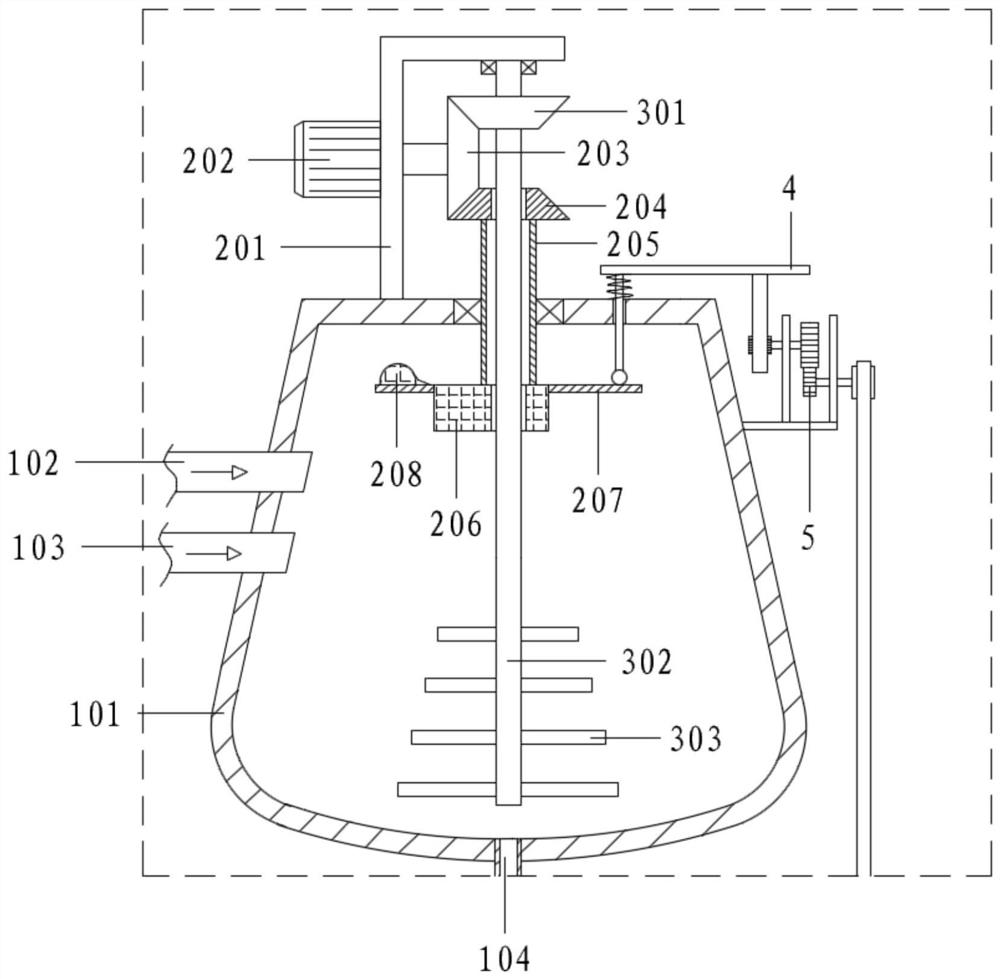
[0065] Referring to the accompanying drawings, a sewage treatment device with automatic slagging function includes a stirring tank 101, a filter chamber 105, a rotating assembly 2, a stirring assembly 3, a jacking assembly 4, an amplifying assembly 5, a transmission assembly 6 and a slagging assembly 7;
[0066] One side of the stirring tank 101 is connected with a sewage inlet pipe 102 and a drug feeding pipe 103; the bottom of the stirring tank 101 is connected with a liquid pipe 104, and the liquid pipe 104 communicates with the left side of the top of the filter chamber 105; the bottom of the filter chamber 105 has a drain A filter screen 107 is installed at the joint of the liquid pipe 106; a slag discharge pipe 108 is also connected to the lower right of the filter chamber 105;
[0067] Stirring tank 101 is provided with stirring component 3, and the top of stirring component 3 extends out of stirring tank 101 and is equipped with rotating component 2; The top of stirrin...
Embodiment 2
[0069] Referring to the accompanying drawings, a sewage treatment device with automatic slagging function includes a stirring tank 101, a filter chamber 105, a rotating assembly 2, a stirring assembly 3, a jacking assembly 4, an amplifying assembly 5, a transmission assembly 6 and a slagging assembly 7;
[0070] One side of the stirring tank 101 is connected with a sewage inlet pipe 102 and a drug feeding pipe 103; the bottom of the stirring tank 101 is connected with a liquid pipe 104, and the liquid pipe 104 communicates with the left side of the top of the filter chamber 105; the bottom of the filter chamber 105 has a drain A filter screen 107 is installed at the joint of the liquid pipe 106; a slag discharge pipe 108 is also connected to the lower right of the filter chamber 105;
[0071] Stirring tank 101 is provided with stirring component 3, and the top of stirring component 3 extends out of stirring tank 101 and is equipped with rotating component 2; The top of stirrin...
Embodiment 3
[0094] On the basis of embodiment 2,
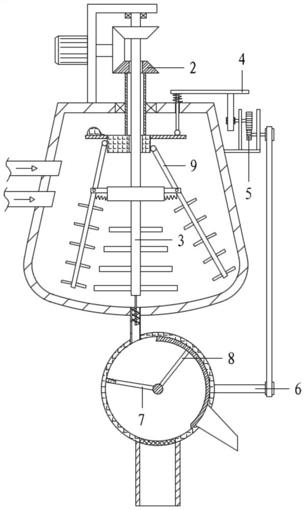
[0095] It also includes a sealing assembly 8; the sealing assembly 8 is arranged in the filter cavity 105, including the second connecting rod 801 and the arc baffle 802;
[0096] An arc-shaped baffle 802 is connected above the rotating shaft 702 through the second connecting rod 801 , and the arc-shaped baffle 802 overlaps with the inner wall of the filter chamber 105 .
[0097] Specifically, referring to the accompanying drawings, when the slag discharge assembly 7 is not working, the arc-shaped baffle 802 is located on the right side and its lower section blocks the entrance of the slag discharge pipe 108, so as to avoid the situation that the sewage flow is too large and directly discharged from the slag discharge pipe 108 appear; and when the slag discharge assembly 7 is working, the rotating shaft 702 also swings synchronously with the arc baffle 802 through the second connecting rod 801, and the arc baffle 802 and the scraper 704 r...
PUM
 Abstract
Description
Claims
Application Information
 - R&D
- Intellectual Property
- Life Sciences
- Materials
- Tech Scout
- Unparalleled Data Quality
- Higher Quality Content
- 60% Fewer Hallucinations
Browse by: Latest US Patents, China's latest patents, Technical Efficacy Thesaurus, Application Domain, Technology Topic, Popular Technical Reports.
© 2025 PatSnap. All rights reserved.Legal|Privacy policy|Modern Slavery Act Transparency Statement|Sitemap|About US| Contact US: help@patsnap.com


