
Intelligent padlock

A padlock, intelligent technology, applied in the field of intelligent padlocks), can solve the problems of reduced production efficiency, increased production cost, difficulty in screwing and installation, etc., and achieve the effect of low production cost, low cost, and convenient installation and production

Inactive Publication Date: 2021-03-12
罗国民
View PDF0 Cites 0 Cited by
  • Summary
  • Abstract
  • Description
  • Claims
  • Application Information

AI Technical Summary

Problems solved by technology

At present, the components such as the motor and the control circuit are respectively installed in the deep main cavity accommodation space of the lock housing by screwing, but due to the overall small size of the lock housing and the width of the housing space to be locked and depth effect, it is very difficult for people to realize the screw installation of electronic components (control circuit) and mechanical parts (motor, etc.) positioning, resulting in a reduction in production efficiency and an increase in production costs

Method used


Image

  • Intelligent padlock
  • Intelligent padlock
  • Intelligent padlock

Examples


Embodiment Construction

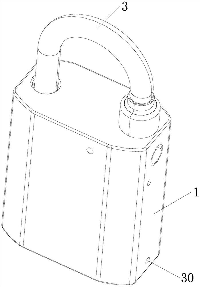
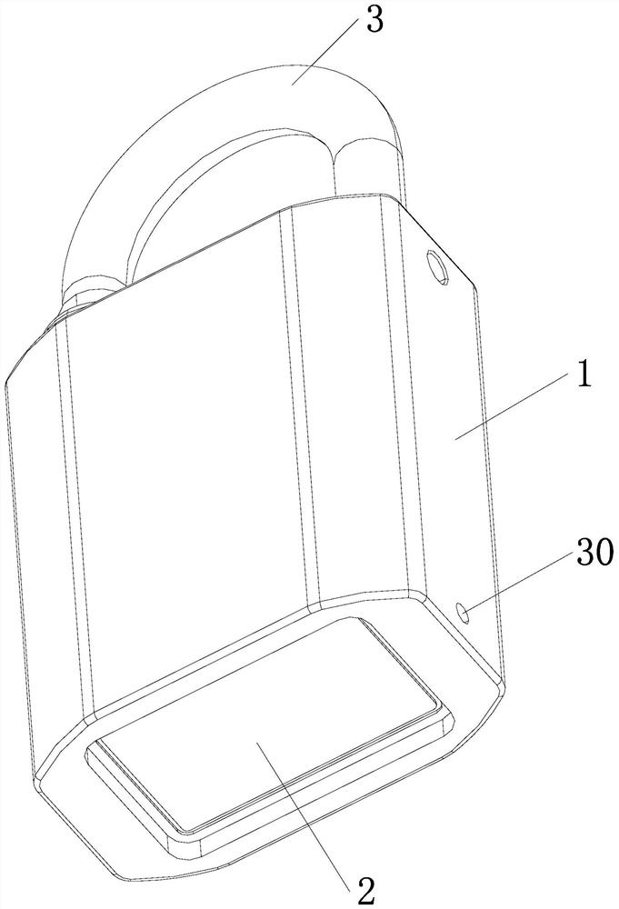
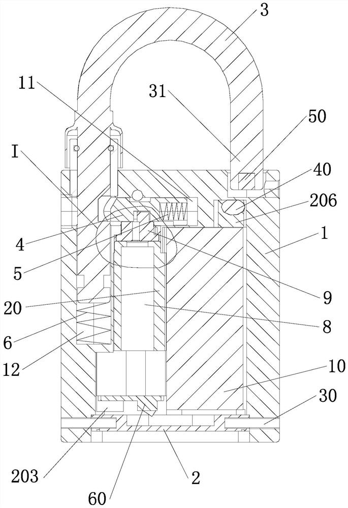
[0024] The present invention is an intelligent padlock, such as Figures 1 to 9 As shown, it includes a lock body 1, a bottom cover 2, a lock ring 3, a lock tongue 4 and a lock tongue spring 5 arranged in a transverse slide groove 11 in the lock body 1, and a lock ring slot 12 arranged in the lock body 1. The lock ring spring 6 of the lock body, the control circuit 7, the motor 8, the unlocking wheel 9 and the accumulator 10 arranged in the lock main control accommodation hole 13 of the lock body, and the antenna (not shown in the figure) arranged on the surface of the lock body When the smart padlock is passive), these structures and working principles are consistent with the current smart padlock, the difference is that the control circuit 7, the motor 8 and the unlocking wheel 9 are installed on the bracket 20 to form the main control of the lock. After the assembly is installed in the main control accommodating hole 13 of the lock, a motor mounting hole 201 for placing the...


PUM


Abstract

The invention discloses an intelligent padlock. The intelligent padlock comprises a lock body, a bottom cover, a lock ring, a lock tongue, a lock tongue spring, a lock ring spring, a control circuit,a motor, an unlocking wheel and an accumulator, wherein after the control circuit, the motor and the unlocking wheel are arranged on a support to form a lock main control component, the lock main control component is arranged in a lock main control containing hole in a modular mode, so that the lock main control component can be put in the lock body after debugging, and compared with the situationthat the lock main control component needs to be put in the lock body to debug the intelligent padlock at the present stage, more convenience is achieved; and furthermore, the support and the accumulator are positioned by the shape of the side wall of the lock main control containing hole in the transverse direction and are pressed and positioned by the bottom cover in the vertical direction, sothat the whole lock main control component and the accumulator do not need to be fixed by screws, and only the bottom cover needs to be fixed in a bolt riveting mode and the like, the situation that the control circuit, the motor and the accumulator can only be fixed through the plurality of screws at the present stage is avoided, the structure is more reasonable, the installation and production are more convenient, and the production cost is lower.

Description

technical field [0001] The invention relates to an intelligent hanging lock (referred to as an intelligent padlock for short). Background technique [0002] Smart padlocks have been widely used outdoors (such as outdoor power facilities and communication facilities). At present, most smart padlocks are mainly divided into three categories, one is a smart padlock with a built-in battery (called an active smart padlock); There is no battery inside, and the padlock is powered by an electronic key; there is also a smart padlock that has no battery inside, and is powered by a dedicated wireless key. The latter two are commonly known as passive smart padlocks. [0003] We know that the components installed in the main cavity of the lock housing include the main control assembly of the lock (which mainly includes a motor, a control circuit and an unlocking wheel) and an accumulator (such as an energy storage capacitor or a battery). At present, the components such as the motor an...

Claims


Application Information

Patent Timeline
Patent Type & Authority Applications(China)
IPC IPC(8): E05B67/00E05B67/02E05B47/00E05B45/06E05B17/00
CPCE05B17/0004E05B45/005E05B47/0012E05B47/0607E05B67/00E05B67/02E05B2047/0058
Inventor 罗国民
Owner 罗国民
Learn More