
Sound insulation equipment with portable mounting function for industrial draught fan

A fan and industrial technology, applied in the field of industrial fans, can solve the problems of low work efficiency, inconvenient installation, easy to generate noise, etc., and achieve the effects of preventing noise damage, convenient loading and unloading, and eliminating noise

Inactive Publication Date: 2021-03-12
徐康
View PDF0 Cites 0 Cited by
  • Summary
  • Abstract
  • Description
  • Claims
  • Application Information

AI Technical Summary

Problems solved by technology

[0003] However, before the industrial fan is used, the fan needs to be installed on the fan base. However, most of the models between the fan and the fan base are unique at present, which makes it impossible to install another type of fan on the fan base, resulting in the use of the fan. Certain limitations, among them, the connection between the fan and the fan base is mostly done by screws, which is not only inconvenient to install but also troublesome to disassemble, resulting in low working efficiency. Not only that, when the fan rotates , the air interacts with the parts at the fan bearings, and it is easy to generate noise. The noise is easy to make people feel upset, and it is not good for the human body. Therefore, a sound insulation device with a portable installation function for industrial fans came into being.

Method used


Image

  • Sound insulation equipment with portable mounting function for industrial draught fan
  • Sound insulation equipment with portable mounting function for industrial draught fan
  • Sound insulation equipment with portable mounting function for industrial draught fan

Examples


Embodiment Construction

[0025] The following will clearly and completely describe the technical solutions in the embodiments of the present invention with reference to the accompanying drawings in the embodiments of the present invention. Obviously, the described embodiments are only some, not all, embodiments of the present invention. Based on the embodiments of the present invention, all other embodiments obtained by persons of ordinary skill in the art without making creative efforts belong to the protection scope of the present invention.

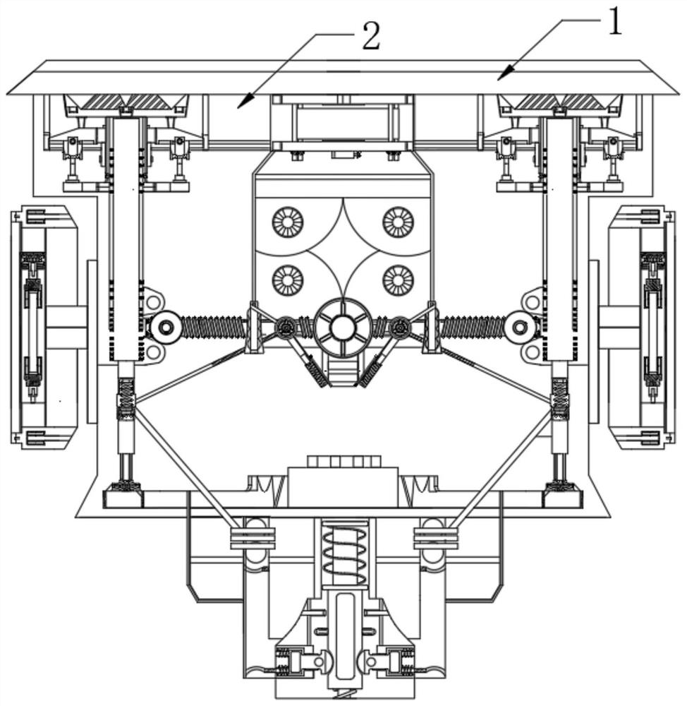
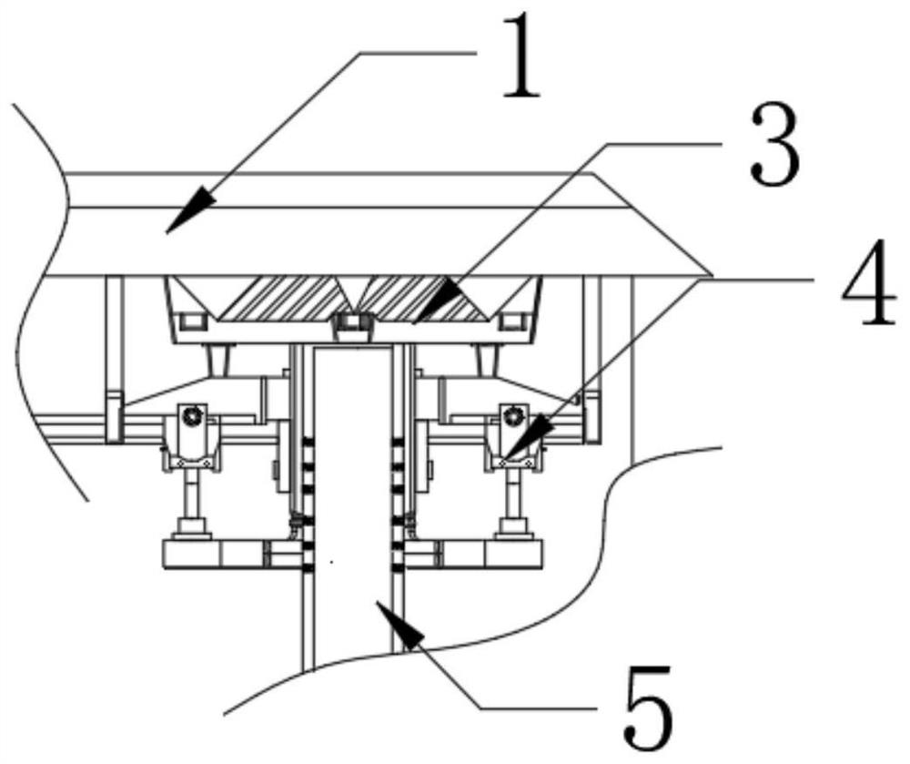
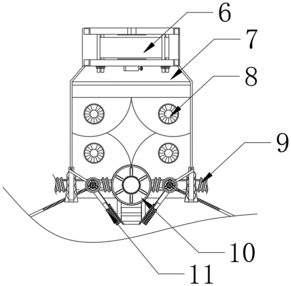
[0026] see Figure 1-5 : A sound insulation device for an industrial fan with a portable installation function, comprising a main body 1, the bottom of the main body 1 is movably connected to a metal seat 2 located in the middle of the support member 5, and a metal seat 2 is movably connected to the outer side of the metal seat 2 and located above the support member 5. Seat 3, this structure has stability and ease of use; the middle of the main body 1 is fixed...


PUM


Abstract

The invention relates to the technical field of industrial draught fans, and discloses sound insulation equipment with a portable mounting function for an industrial draught fan. Mounting seats are movably connected to the left side and the right side of a metal seat, and protective parts are movably connected to the outer sides of the mounting seats. According to the sound insulation equipment with the portable mounting function for the industrial draught fan, a movable part rotates anticlockwise to drive a screw to operate synchronously, the protective parts play a role in stabilizing, the movable part is engaged with the screw, matched textures are arranged on the movable part and the screw, an action part plays a role in stabilizing, the screw drives a rotating shaft to operate synchronously, and spacing strips operate along with the rotating shaft; the screw rotates and is pulled into bases to operate, the bases are driven towards the middle and get close to the middle, the rotating shaft rotates along with rotation of the bases, the adjusting effect is achieved, and therefore the draught fan above the spacing strips and the bases on the two sides are connected together; and the range of the bases is wide, use limitation is greatly improved, operation is easy, design is reasonable, and the effect of convenient assembly and disassembly is achieved.

Description

technical field [0001] The invention relates to the technical field of industrial fans, in particular to a sound insulation device for industrial fans with a portable installation function. Background technique [0002] Fan is China's customary abbreviation for gas compression and gas conveying machinery. Industrial fans refer to fans that are specially used for ventilation and high-temperature smoke exhaust in tunnels, underground garages, high-level civil buildings, metallurgy, factories and mines, etc., with high-efficiency cooling and cooling. The cooling coil, the key part of the machine, is composed of advanced fin shape and heat exchange tubes, adopts new tube expansion technology, advanced design structure of variable fin distance on the air outlet surface, and staggered arrangement of heat exchange tubes to ensure perfect air flow organization , the air distribution is even and reasonable, realizing efficient heat exchange, not easy to frost, and efficient, simple a...

Claims


Application Information

Patent Timeline
IPC IPC(8): F04D29/66F04D29/60
CPCF04D29/601F04D29/663F04D29/664F04D29/668
Inventor 徐康
Owner 徐康
Learn More