Eureka AIR delivers breakthrough ideas for toughest innovation challenges, trusted by R&D personnel around the world.

Reduction equipment for increasing use frequency of bearing of compressor and use method thereof

A compressor and bearing technology, applied in the field of cutting equipment, can solve problems such as affecting rolling friction, poor quality, and troublesome ball bearing replacement.

Inactive Publication Date: 2021-03-12
舒适
View PDF0 Cites 1 Cited by
  • Summary
  • Abstract
  • Description
  • Claims
  • Application Information

AI Technical Summary

Problems solved by technology

[0004] Since ball bearings are consumables, pitting corrosion will occur after a period of use. If there are problems such as poor quality, when a certain number of uses is reached, the stress will change those problematic contact surfaces, so that some parts will appear fish-like fatigue spalling points; at this time, the bearing will also lose the energy efficiency of the design. Can't continue running smoothly and smoothly
[0005] However, once the ball bearings used in the equipment are damaged, it is more troublesome to replace, and the damage is not easy to be detected; in addition, another reason for the pitting phenomenon is that when the bearings are lubricated again, the moisture or impurities in the lubricating oil are not present. It is cleaned and attached between the bearing and the ball, which affects the rolling friction between the two. Therefore, a reduction device that increases the number of times the compressor is used for the bearing came into being.

Method used


Image

  • Reduction equipment for increasing use frequency of bearing of compressor and use method thereof
  • Reduction equipment for increasing use frequency of bearing of compressor and use method thereof
  • Reduction equipment for increasing use frequency of bearing of compressor and use method thereof

Examples


Embodiment Construction

[0026] The following will clearly and completely describe the technical solutions in the embodiments of the present invention with reference to the accompanying drawings in the embodiments of the present invention. Obviously, the described embodiments are only some, not all, embodiments of the present invention. Based on the embodiments of the present invention, all other embodiments obtained by persons of ordinary skill in the art without making creative efforts belong to the protection scope of the present invention.

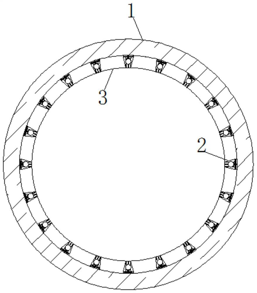
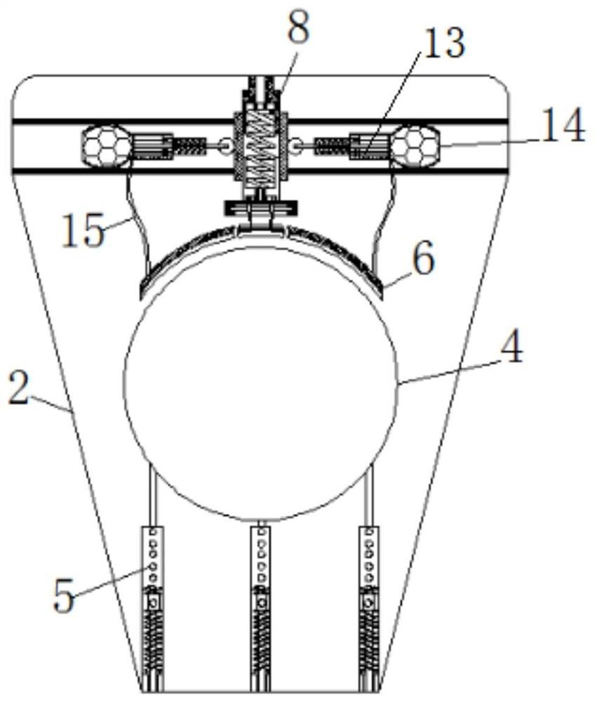
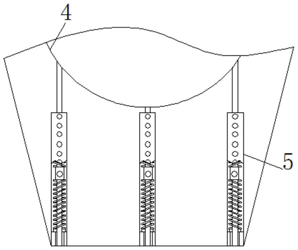
[0027] see Figure 1-8 , a kind of reducing equipment and using method for improving the number of times of use of bearings used in compressors, comprising an outer base 1, a ball box 2 is movably connected to the inside of the outer pedestal 1, and the side of the ball box 2 away from the outer pedestal 1 is movably connected There is an inner base 3, and the inside of the ball box 2 is provided with a placement groove 4, and the bottom of the placement groov...


PUM


Abstract

The invention relates to the technical field of compressor part transformation, and discloses a reduction device for increasing the use frequency of a bearing of a compressor and a use method thereof.The reduction device comprises an outer base, a ball box is movably connected to the interior of the outer base, an inner base is movably connected to the side, away from the outer base, of the ballbox, a containing groove is formed in the ball box, spring rods are movably connected to the bottoms of the containing groove, a scraper is movably connected to the top of the containing groove, a buffer frame is movably connected to the side, away from the containing groove, of the scraper, that is to say, a force exerted on compression springs and the spring rods by balls in the containing groove is not uniform any more, the force exerted on the containing groove is not balanced any more, the spring rods are pushed to move in the direction close to the scraper, the ball make contact with thescraper, the scraper cuts the ball into a smooth state again, and therefore the effect of cutting the ball into a round shape again when the ball is not smooth any more is achieved; and when the sizeof the ball in the containing groove is reduced, the ball is attached to the containing groove again, and normal use of the bearing is not affected.

Description

[0001] This application is a divisional application with an application date of November 28, 2019, an application number of CN 201911190010.5, and the title of the invention is a device for reducing the number of bearings used in compressors. technical field [0002] The invention relates to the technical field of transformation of compressor parts, in particular to a reduction device for increasing the number of times of use of compressor bearings and a method for using the same. Background technique [0003] Ball bearings are commonly used in compressors, which is a kind of rolling bearings. The method of use is to install spherical alloy steel balls in the middle of the inner steel ring and the outer steel ring to reduce friction during power transmission and improve The transmission efficiency of mechanical power. [0004] Since ball bearings are consumables, pitting corrosion will occur after a period of use. If there are problems such as poor quality, when a certain n...

Claims


Application Information

Patent Timeline
Patent Type & Authority Applications(China)
IPC IPC(8): F16C33/30F16C33/66F04B39/00F04B39/02
CPCF04B39/00F04B39/02F16C33/30F16C33/6637
Inventor 舒适
Owner 舒适
Why Eureka
Eureka Blog
Learn More