Shaping tool equipment for controlling transformer parts

A technology for tooling equipment and transformers, applied in coil manufacturing and other directions, can solve problems such as inconvenience to meet the needs of shaping processing, reduced applicability and ease of use of shaping tooling, and difficulty in replacing different shaping punches.

Inactive Publication Date: 2021-03-12
南京多脉智能设备有限公司
View PDF0 Cites 0 Cited by
  • Summary
  • Abstract
  • Description
  • Claims
  • Application Information

AI Technical Summary

Problems solved by technology

[0004] The object of the present invention is to provide a tooling equipment for controlling the shaping of transformer parts, by setting the frame assembly, punch assembly, carrier assembly, die assembly, limit assembly, chassis assembly and flatten assembly to solve the problem of In the above-mentioned background technology, it is difficult to replace different integral punch frames during the use of the traditional control transformer component shaping tool, which leads to the reduction of the applicability and convenience of the shaping tool, and it is not convenient to meet the requirements of different control transformer components. Due to the requirements of plastic processing, it is not possible to level the component molds in advance, and the wrinkled part of the component molds affects the quality of plastic processing

Method used


Image

  • Shaping tool equipment for controlling transformer parts
  • Shaping tool equipment for controlling transformer parts
  • Shaping tool equipment for controlling transformer parts

Examples


Embodiment Construction

[0031] The present invention will be further described below in conjunction with the examples.

[0032] The following examples are used to illustrate the present invention, but cannot be used to limit the protection scope of the present invention. The conditions in the embodiment can be further adjusted according to the specific conditions, and the simple improvement of the method of the present invention under the premise of the concept of the present invention belongs to the protection scope of the present invention.

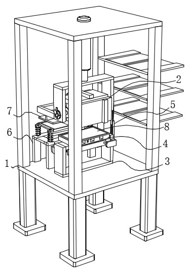
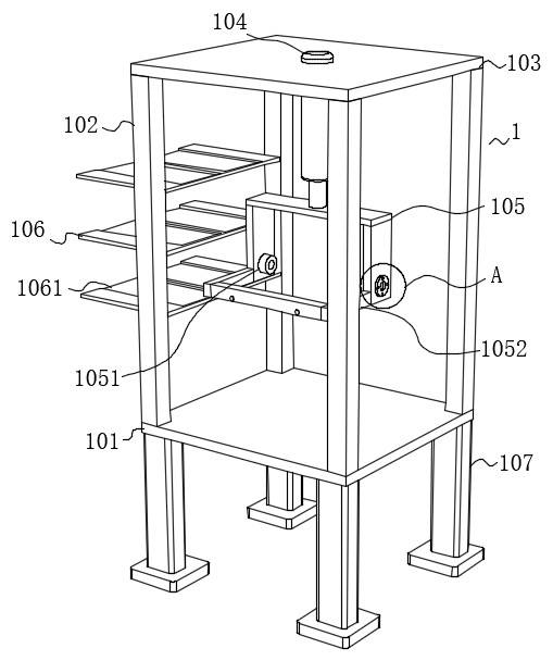
[0033] see Figure 1-10 , the present invention provides a tooling equipment for controlling the shaping of transformer components, including a frame assembly 1, a punch assembly 2 is arranged on the inside of the frame assembly 1, and the inside of the frame assembly 1 is located directly below the punch assembly 2. There is a carrier assembly 3, the upper end of the carrier assembly 3 is provided with a die assembly 4, the side of the carrier assembly 3 is ...


PUM


Abstract

The invention discloses shaping tool equipment for controlling transformer parts, and belongs to the technical field of shaping of transformer accessories. The shaping tool equipment comprises a rackassembly, a male die assembly is arranged on the inner side of the rack assembly, a carrier assembly is arranged in the inner side of the rack assembly and located under the male die assembly, a female die assembly is arranged at the upper end of the carrier assembly, a limiting assembly is arranged on the side face of the carrier assembly, a bottom frame assembly is arranged on the side, close tothe carrier assembly, of the inner side of the rack assembly, and a flattening assembly is arranged in the inner side of the rack assembly and located over the bottom frame assembly. According to theshaping tool, different shaping male die frames can be conveniently selected and replaced, the applicability and the use convenience of the shaping tool can be improved, different shaping machining requirements suitable for controlling transformer components can be met, shaping machining treatment can be conducted, meanwhile, leveling treatment can be conducted on a to-be-shaped component die piece in advance, influence of wrinkled parts of the component mold pieces on the shaping processing quality is effectively prevented, and the shaping working efficiency of the transformer component is improved.

Description

technical field [0001] The invention belongs to the technical field of shaping of transformer accessories, and in particular relates to tooling equipment for controlling shaping of transformer parts. Background technique [0002] A transformer is a device that uses the principle of electromagnetic induction to change AC voltage. Its main components are primary coils, secondary coils and iron cores (magnetic cores). The main functions of the transformer are: voltage conversion, current conversion, impedance conversion, isolation, voltage stabilization (magnetic saturation magnetic saturation transformer), etc., according to the purpose can be divided into: power transformer power transformer and special transformer, in electrical equipment and wireless circuits, Transformers are often used for step-down voltage, matching impedance, safety isolation, etc. In a generator, whether the coil moves through the magnetic field or the magnetic field moves through the fixed coil, an e...

Claims


Application Information

Patent Timeline
Patent Type & Authority Applications(China)
IPC IPC(8): H01F41/04
CPCH01F41/04
Inventor 龙继良
Owner 南京多脉智能设备有限公司
Why Eureka
Try Eureka