
Vital sign monitoring equipment, system and method

A technology of vital signs and monitoring equipment, applied in medical science, sensors, measuring pulse rate/heart rate, etc., can solve the problems of low monitoring efficiency, increase the labor intensity of medical staff, and consume working time of medical staff, so as to improve efficiency, Intuitive effect of display status

Pending Publication Date: 2021-03-16
SHANGHAI KOHDEN MEDICAL ELECTRONIC INSTRUMENT CORPORATION
View PDF0 Cites 0 Cited by
  • Summary
  • Abstract
  • Description
  • Claims
  • Application Information

AI Technical Summary

Problems solved by technology

[0002] Vital sign monitoring equipment is a very important monitoring equipment in clinical nursing work. It is used for real-time monitoring of dynamic changes in patient vital signs. Due to the busy work of the existing medical staff when patrolling the ward, one medical staff needs to monitor multiple patients at the same time. , while the existing vital sign monitoring equipment requires medical personnel to carefully observe the display interface of the equipment to judge the patient's vital sign information data and whether the test is over. Repeatedly observe the work of the device interface again. This monitoring method greatly consumes the working time of medical staff, increases the labor intensity of medical staff, and makes the monitoring efficiency relatively low.

Method used


Image

  • Vital sign monitoring equipment, system and method
  • Vital sign monitoring equipment, system and method
  • Vital sign monitoring equipment, system and method

Examples


Embodiment 1

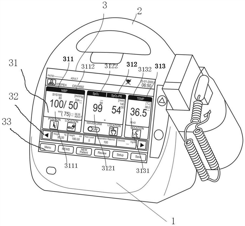
[0067] Such as figure 1 As shown, a vital sign monitoring device is provided, and its automatic display area 31 includes a non-invasive blood pressure display area (abbreviation: NIBP) 311, arterial blood oxygen saturation (abbreviation: SpO2) and pulse rate (abbreviation: SpO2-PR) display area 312. Body temperature (abbreviation: TEMP) display area 313. Three types.

[0068] Wherein the non-invasive blood pressure display area 311 includes a non-invasive blood pressure numerical display area 3111 and a non-invasive blood pressure display label 3112, and the arterial blood oxygen saturation and pulse rate display area 312 includes an arterial blood oxygen saturation and pulse rate numerical display area 3121 and an arterial blood oxygen saturation and pulse rate display label 3122; the body temperature display area 313 includes a body temperature numerical display area 3131 and a body temperature display label 3132; where the display labels in each display area are located abo...

Embodiment 2

[0088] The main difference between Embodiment 2 and Embodiment 1 is that the automatic display area of ​​the vital sign monitoring device includes two types of vital sign information display areas, namely: non-invasive blood pressure display area 311 and arterial blood oxygen saturation and pulse rate display area 312, There is no body temperature display area 313 . The widths of the two vital sign information display areas in the display interface are automatically scaled and adjusted according to the number of vital sign information display areas. At this time, each display label is equal to the width of the corresponding numerical display area.

[0089] Such as Figure 8 As shown, it is the interface diagram of the display screen before the patient’s vital sign information is measured in the second embodiment, in which the non-invasive blood pressure value display area 3111, the arterial blood oxygen saturation and pulse rate value display area 3121 have no specific data va...


PUM


Abstract

The invention discloses vital sign monitoring equipment. The vital sign monitoring equipment comprises an equipment body (1), a handle (2) and a display screen (3) which arranged on the equipment body(1); the display screen (3) includes an automatic display area (31), a manual display area (32) and a function menu area (33); the automatic display area (31) includes at least two vital sign information display areas of a patient; the manual display area (32) includes at least one body health parameter display area of the patient; and the function menu area (33) is a function menu operation areaof the equipment body (1). A monitoring system and monitoring method corresponding to the vital sign monitoring equipment are further disclosed. According to the monitoring equipment, the vital signinformation of the patient can be automatically displayed, and whether measurement is completed or not is automatically displayed by arranging the vital sign display labels in a row; the display is more visual through color identification, and measurement error information can be quickly obtained, so that the medical monitoring work is clear at a glance.

Description

technical field [0001] The invention belongs to the field of medical equipment, and in particular relates to a vital sign monitoring equipment, system and method. Background technique [0002] Vital sign monitoring equipment is a very important monitoring equipment in clinical nursing work. It is used for real-time monitoring of dynamic changes in patient vital signs. Due to the busy work of the existing medical staff when patrolling the ward, one medical staff needs to monitor multiple patients at the same time. , while the existing vital sign monitoring equipment requires medical personnel to carefully observe the display interface of the equipment to judge the patient's vital sign information data and whether the test is over. Repeatedly observe the work of the device interface again. This monitoring method greatly consumes the working time of the medical staff, increases the labor intensity of the medical staff, and makes the monitoring efficiency relatively low. Conte...

Claims


Application Information

Patent Timeline
IPC IPC(8): A61B5/0205A61B5/1455A61B5/00
CPCA61B5/02055A61B5/0225A61B5/024A61B5/14542A61B5/1455A61B5/742A61B5/743A61B5/7435A61B5/7445
Inventor 村田史郎
Owner SHANGHAI KOHDEN MEDICAL ELECTRONIC INSTRUMENT CORPORATION
Learn More