
Vacuum sputtering gap measuring device

A measuring device and vacuum sputtering technology, applied in the direction of measuring devices, optical devices, instruments, etc., can solve the problems of poor measurement accuracy and inflexible adjustment of measurement tools, and achieve the effect of improving accuracy

Inactive Publication Date: 2021-03-16
苏州科亿嘉科技发展有限公司
View PDF6 Cites 0 Cited by
  • Summary
  • Abstract
  • Description
  • Claims
  • Application Information

AI Technical Summary

Problems solved by technology

[0004] The purpose of the present invention is to provide a vacuum sputtering gap measurement device to solve the problem that the measurement tool proposed in the above background technology cannot be flexibly adjusted according to changes in the use environment, resulting in poor measurement accuracy

Method used


Image

  • Vacuum sputtering gap measuring device
  • Vacuum sputtering gap measuring device
  • Vacuum sputtering gap measuring device

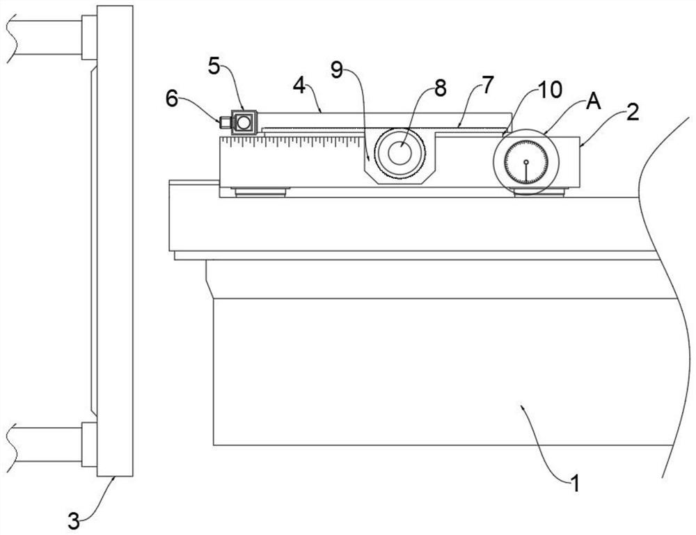
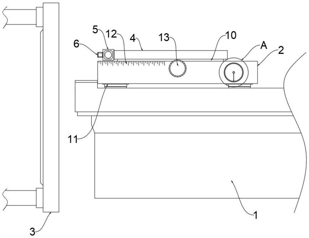
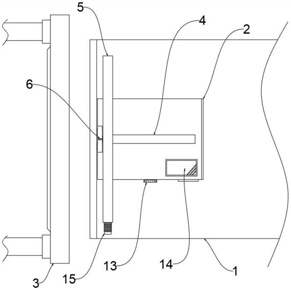
Examples


Embodiment Construction

[0023] The following will clearly and completely describe the technical solutions in the embodiments of the present invention with reference to the accompanying drawings in the embodiments of the present invention. Obviously, the described embodiments are only some, not all, embodiments of the present invention.

[0024] see Figure 1-7 , an embodiment provided by the present invention: a vacuum sputtering gap measurement device, including a workbench 1, a movable plate 3 is arranged on one side of the workbench 1, a measuring device 2 is arranged on the upper end of the workbench 1, and the measuring device 2 A slide rail 10 is installed at the middle position of the upper end, and an adjustment housing 4 is installed outside the slide rail 10, and the adjustment housing 4 is slidably connected with the slide rail 10, and the end of the adjustment housing 4 close to the movable plate 3 is fixedly provided with a displacement mechanism 5, and the displacement An infrared dista...


PUM


Abstract

The invention discloses a vacuum sputtering gap measuring device, relates to the technical field of vacuum sputtering, and aims at solving the problem that an existing measuring tool cannot be flexibly adjusted according to the change of the using environment, so that the measuring accuracy is poor. A movable plate is arranged on one side of a workbench, a measuring device is arranged at the upperend of the workbench, a sliding rail is installed in the middle of the upper end of the measuring device, an adjusting shell is installed outside the sliding rail, the adjusting shell is in sliding connection with the sliding rail, a displacement mechanism is fixedly arranged at the end, close to the movable plate, of the adjusting shell, an infrared distance measuring sensor is installed on oneside of the displacement mechanism, a horizontal mechanism is fixedly arranged on one side of the measuring device, bases are arranged at the four corners of the lower end of the workbench, and scalemarks are arranged at the upper end of one side of the measuring device.

Description

technical field [0001] The invention relates to the technical field of vacuum sputtering, in particular to a vacuum sputtering gap measuring device. Background technique [0002] Vacuum magnetron sputtering technology refers to a method that uses the magnetic field matched with the surface of the cathode to form electron traps, so that electrons drift close to the surface of the cathode under the action of E×B, and set a magnetic field orthogonal to the electric field of the target surface. The fast electrons move approximately cycloidally in an orthogonal electromagnetic field, which increases the electron travel and improves the ionization rate of the gas. At the same time, high-energy particles lose energy after colliding with the gas, and the substrate temperature is low. Coating can be completed. When performing magnetron sputtering, the substrate is on the upper end of the workbench, and a movable plate is connected to the side of the equipment cavity, which mainly con...

Claims


Application Information

Patent Timeline
Patent Type & Authority Applications(China)
IPC IPC(8): G01B11/14
CPCG01B11/14
Inventor 戴丽娜
Owner 苏州科亿嘉科技发展有限公司
Learn More