
Measuring device and method for continuous distribution of pore pressure and quantitative evaluation method for tensile stress

A technology of pore pressure and measuring device, which is applied in the direction of fluid pressure measurement, measuring device, and measuring force components through thermal devices, which can solve the inaccurate distribution of pore pressure, affect the calculation of tensile stress, and lack of consideration of the finite size of poroelasticity Problems such as the wall tube model to achieve the effect of ensuring accuracy and ensuring accurate prediction

Active Publication Date: 2021-09-03
XI'AN PETROLEUM UNIVERSITY
View PDF0 Cites 0 Cited by
  • Summary
  • Abstract
  • Description
  • Claims
  • Application Information

AI Technical Summary

Problems solved by technology

[0005] ①Replacing the continuous pore pressure along the pore pressure with the pore pressure at discrete points along the way, resulting in inaccurate distribution of pore pressure and affecting the final calculation of tensile stress;
[0006] ②Because the pressure transmitter is distributed on the surface of the porous medium, what is actually measured is the wall pore pressure between the porous medium and the cylinder body. The pore pressure here is obviously affected by the surface roughness of the cylinder body and cannot be measured. Truly reflect the pore pressure distribution inside the porous medium
[0008] ①The radial stress analytical expression currently used is the infinite thick-walled tube model. In fact, the outer boundary of the oil and gas reservoir simulated by laboratory experiments must be finite, and there is no finite thick-walled tube model considering poroelasticity.

Method used


Image

  • Measuring device and method for continuous distribution of pore pressure and quantitative evaluation method for tensile stress
  • Measuring device and method for continuous distribution of pore pressure and quantitative evaluation method for tensile stress
  • Measuring device and method for continuous distribution of pore pressure and quantitative evaluation method for tensile stress

Examples


Embodiment 1

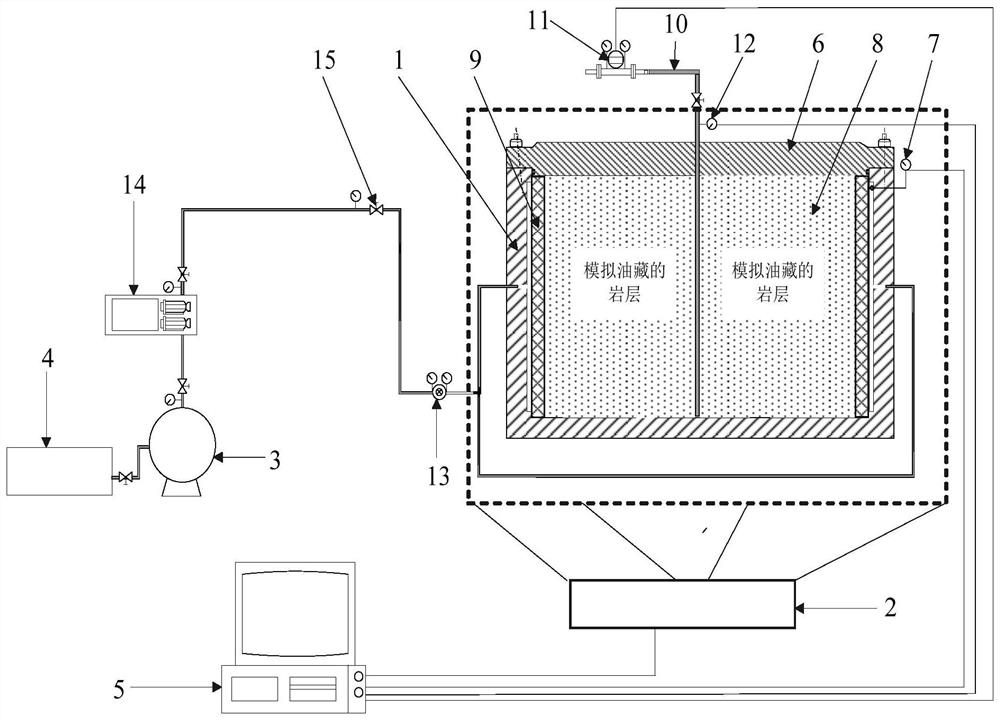
[0052] The invention provides a device for continuously measuring pore pressure distribution, specifically as figure 1 As shown, it includes a cylinder body 1, a thermal imaging instrument 2, a compressor 3, an air tank 4 and a data acquisition system 5;

[0053]The cylinder body 1 is a cylindrical structure, the top of the cylinder body 1 is provided with a cylinder head 6, and one side thereof is provided with an inlet; the inlet is provided with a gas inlet pressure sensor 7, and the cylinder body 1 is provided with a simulated rock formation 8, and the simulated rock formation 8 and A high-permeability iron mesh 9 is arranged between the inner walls of the cylinder body 1; the cylinder body 1 is used to simulate a gas reservoir, and the gas flows into the rock formation from the inner wall of the cylinder body 1 and flows out from the middle pipeline, forming a radial flow.

[0054] The simulated rock formation 8 in the cylinder body 1 is provided with a gas detection pipe...


PUM


Abstract

The invention provides a device and method for measuring continuous distribution of pore pressure and a quantitative evaluation method for tensile stress, belonging to the field of solid-phase output control of deep high-pressure gas wells. The device includes a cylinder body, a thermal imaging instrument, a compressor, a gas tank and data acquisition system, the inlet of the cylinder is provided with a gas inlet pressure sensor, the gas outlet is provided with a gas outlet pressure sensor, the gas inlet pressure sensor, the gas outlet pressure sensor, the flow sensor and the thermal imaging instrument are all connected to the data acquisition system through a data line connect. This method starts from the method of accurately predicting pore pressure, and considers the tensile stress caused by poroelasticity and fluid drag at the same time, and finally obtains the accurate radial tensile stress. Based on the tensile failure criterion, the solid phase production conditions are guaranteed Accurate prediction, obtaining continuous pore pressure distribution equations from experiments, ensures the accuracy of tensile stress calculation.

Description

technical field [0001] The invention relates to the technical field of solid-phase production control of deep high-pressure gas wells, in particular to a device and method for measuring continuous distribution of pore pressure and a quantitative evaluation method for tensile stress. Background technique [0002] Since the fractured formation is a fluid-solid coupling system, the change of fluid pressure during test production will cause the change of effective stress, and the effective stress exceeding the strength of rock is the result of solid phase production due to the instability of open holes or perforated holes during test production. root cause. In fact, the fluid-solid coupling is controlled by the coupling of two factors, the deformation of the skeleton in the medium and the change of the fluid volume in the pores. That is, the pore pressure and the stress of the skeleton in the fluid-solid coupling system of fractured reservoirs interact with each other, resulting...

Claims


Application Information

Patent Timeline
Patent Type & Authority Patents(China)
IPC IPC(8): G01L11/00G01L5/16
CPCG01L5/16G01L11/002
Inventor 姜海龙赵凯窦亮彬毕刚
Owner XI'AN PETROLEUM UNIVERSITY
Learn More