Kinetic energy transmission shaft strength detection equipment for wind power generation
A technology of strength detection and transmission shaft, which is applied in the direction of applying stable torque to test the strength of materials, measuring devices, and testing of mechanical parts, etc. The effect of improving usability and reliability
- Summary
- Abstract
- Description
- Claims
- Application Information
AI Technical Summary
Problems solved by technology
Method used
Image


Examples
Embodiment Construction
[0018] The specific implementation manners of the present invention will be further described in detail below in conjunction with the accompanying drawings and embodiments. The following examples are used to illustrate the present invention, but are not intended to limit the scope of the present invention.
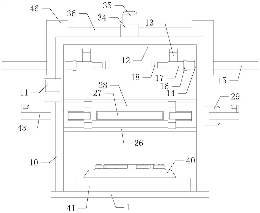
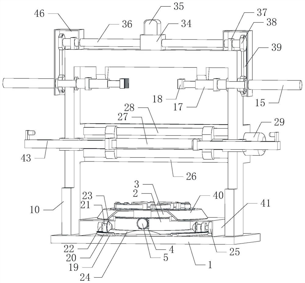
[0019] Such as Figure 1 to Figure 4 As shown, the kinetic energy transmission shaft strength detection device for wind power generation of the present invention, when it is working, puts the bottom of the kinetic energy transmission shaft processed by the outside into the positioning groove in the turntable 2, the transmission shaft remains vertical, and the transmission shaft The lower side of the outer wall of the positioning groove is in contact with the lower side of the inner wall of the positioning groove. The central control box 11 controls the opening of the electromagnetic absorber. The electromagnetic force is generated on the electromagnetic absorber and the bo...
PUM
 Abstract
Description
Claims
Application Information
PatSnap Eureka turns technology decisions into work you can execute. Powered by our Innovation Knowledge Graph, it runs expert workflows across engineering, life sciences, materials and intellectual property. Get your review-ready output in minutes.


