High-voltage electroscope clamping hook

An electroscope and clip hook technology, applied in the field of electric power, can solve the problems such as insufficient contact between the electroscope hook and the electroscope conductive head, and achieve the effects of accurate and reliable electroscope results and increased contact area.

Pending Publication Date: 2021-03-16
GUANGDONG POWER GRID CO LTD +1
View PDF5 Cites 0 Cited by
  • Summary
  • Abstract
  • Description
  • Claims
  • Application Information

AI Technical Summary

Problems solved by technology

[0006] In order to overcome the defect of insufficient contact between the electroscope hook and the electroscope co

Method used


Image

  • High-voltage electroscope clamping hook
  • High-voltage electroscope clamping hook

Examples


Embodiment 1

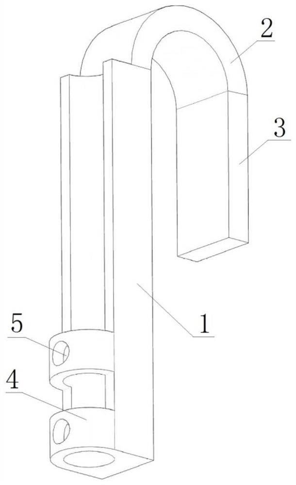
[0029] This embodiment provides a kind of high voltage electroscope clip hook, such as figure 1 As shown, the clip hook includes: a first hook arm 1, a second hook arm 3, and an arc connector 2;

[0030] The upper end of the first hook arm 1 is connected to one end of the arc-shaped connector 2, and the other end of the arc-shaped connector 2 is connected to the second hook arm 3, so that the clip hook is U-shaped;

[0031] The front of the first hook arm 1 is opposite to the front of the second hook arm 3, and the back of the first hook arm 1 is provided with a guide groove along the vertical direction;

[0032] The lower end of the first hook arm 1 is provided with a connecting ring 4, and the connecting ring 4 communicates with the guide groove.

[0033] The guide groove is a semicircular guide groove. The guide groove is arranged coaxially with the connecting ring 4, and the radius of the connecting ring 4 is equal to the radius of the guide groove.

[0034] The number ...

Embodiment 2

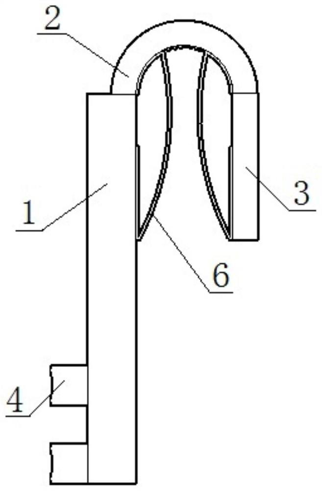
[0038] This embodiment provides a kind of high voltage electroscope clip hook, such as figure 2 As shown, the clip hook includes: a first hook arm 1, a second hook arm 3, and an arc connector 2;

[0039] The upper end of the first hook arm 1 is connected to one end of the arc-shaped connector 2, and the other end of the arc-shaped connector 2 is connected to the second hook arm 3, so that the clip hook is U-shaped;

[0040] The front of the first hook arm 1 is opposite to the front of the second hook arm 3, and the back of the first hook arm 1 is provided with a guide groove along the vertical direction;

[0041] The lower end of the first hook arm 1 is provided with a connecting ring, and the connecting ring 4 communicates with the guide groove.

[0042] The guide groove is a semicircular guide groove.

[0043] The guide groove is arranged coaxially with the connecting ring 4, and the radius of the connecting ring 4 is equal to the radius of the guide groove.

[0044] The...


PUM


Abstract

The invention relates to a high-voltage electroscope clamping hook. The clamping hook comprises a first hook arm, a second hook arm and an arc-shaped connecting piece; the upper end of the first hookarm is connected with one end of the arc-shaped connecting piece, and the other end of the arc-shaped connecting piece is connected with the second hook arm, so that the clamping hook is U-shaped; thefront face of the first hook arm and the front face of the second hook arm are oppositely arranged, and a guide groove is formed in the back face of the first hook arm in the vertical direction; anda connecting ring is arranged at the lower end of the first hook arm and communicated with the guide groove. An electroscope conductive head is fixed by arranging the connecting ring, and the contactarea of the clamping hook and the electroscope conductive head is increased by arranging the guide groove, so it is guaranteed that the electroscope result is more accurate and reliable.

Description

technical field [0001] The invention relates to the field of electric power, in particular to a clip hook for a high voltage electroscope. Background technique [0002] In the operation and maintenance of power transmission and distribution lines, it is often necessary to change the line from the running state to the maintenance state. In order to ensure the safety of the operators, it is necessary to conduct an electrical inspection before adding the grounding wire. At present, the acousto-optic electroscope used in the power industry has the advantages of simple structure and convenient operation. However, in the actual operation process, the operator uses the current electrical inspection equipment to confirm that there is no voltage after the electrical inspection, and then connects the ground wire. There is obviously a certain time interval in this operation process, and the seamless connection cannot be truly achieved. The line may be electrified due to reverse power ...

Claims


Application Information

Patent Timeline
IPC IPC(8): G01R1/04
CPCG01R1/0408G01R1/0416
Inventor 梁华兴董家茂吴东名张亚华吴光贵
Owner GUANGDONG POWER GRID CO LTD
Why Eureka
Try Eureka