Management method of edge equipment and related device
An edge device and management method technology, applied in the computer field, can solve the problems of cumbersome deployment process, affecting the expansion efficiency of edge devices, and high cost
Pending Publication Date: 2021-03-16
TENCENT TECH (SHENZHEN) CO LTD
0 Cites 5 Cited by
AI-Extracted Technical Summary
Problems solved by technology
[0004] However, creating a cluster requires the preparation of machines on the cluster control plane, and then deploying the cluster, that is, deploying from the...
Method used
Instructions are issued by the central control equipment in the cloud, so that the k8s business cluster (i.e. the mode of kube on kube) is created and managed by the k8s meta-cluster, so that the number of managed k8s business clusters can be rapidly increased to increase the cloud control node, And register the edge device to the managed business cluster control node to realize the management of the edge device in the cloud.
[0089] Embodiments of the present application provide a management method of edge devices and related devices, which can be applied to systems or programs that include management functions of edge devices in terminal devices, and determine the elements deployed on the cloud platform in response to target instructions Cluster, the meta-cluster includes a central control device and at least one associated hosting cluster, the central control device is used to issue target instructions to the hosting cluster, and at least one control component is configured in the hosting cluster; then obtain the edge device to be deployed; and then The edge device is associated with the control component, so as to deploy the edge service corresponding to the target instruction on the edge device. In this way, the process of rapidly expanding and managing edge devices is realized. Since edge devices are managed through the control components in the hosting cluster, there is no need to redeploy the upper-layer meta-cluster framework during the cluster expansion process, which improves the expansion efficiency of edge devices.
[0105] It can be understood that the method provided by this application can be written as a program, as a processing logic in the hardware system, or as a management device for edge devices, using integrated or external way to implement the above processing logic. As an implementation, the management device of the edge device determines the meta-cluster deployed on the cloud platform in response to the target instruction, the meta-cluster includes the central control device and at least one associated hosting cluster, and the central control device is used to provide Issue the target instruction, configure at least one control component in the hosting cluster; then obtain the edge device to be deployed; then associate the edge device with the control component to deploy the edge service corresponding to the target instruction on the edge device. In this way, the process of rapidly expanding and managing edge devices is realized. Since edge devices are managed through the control components in the hosting cluster, there is no need to redeploy the upper-layer meta-cluster framework during the cluster expansion process, which improves the expansion efficiency of edge devices.
[0112] Compared with the way of managing edge devices in the cloud cluster dimension in the prior art, this application is equivalent to dividing the cloud cluster, and adjusting the single-layer control of the control device to the node to include the meta-cluster (control device control) Hierarchical structure with managed cluster (node control), which facilitates the management of edge devices. For example, in the k8s scenario, k8smaster adjusts the single-layer control of node to the level of meta-cluster and managed cluster (configure master component in node) formula structure.
[0119] Optionally, in order to facilitate the management of the edge devices by the hosting cluster, you can select ones with similar locations; that is, first...
Abstract
The invention discloses a management method of edge equipment and a related device, and is applied to the technical field of cloud. A meta-cluster deployed on a cloud platform is determined in response to a target instruction, the meta-cluster comprises a central control device and at least one associated hosting cluster, the central control device is used for issuing the target instruction to thehosting cluster, and at least one control component is configured in the hosting cluster; edge equipment to be deployed is acquired; and the edge device is associated with the control component so asto deploy an edge service corresponding to the target instruction at the edge device. Therefore, the process of quickly expanding and managing the edge equipment is achieved, and the edge equipment is managed through the control component in the hosting cluster, so that the meta-cluster framework on the upper layer does not need to be redeployed in the cluster expansion process, and the expansionefficiency of the edge equipment is improved.
Application Domain
Resource allocation
Technology Topic
Operating systemComputer engineering +1
Image
Examples
- Experimental program(1)
Example Embodiment
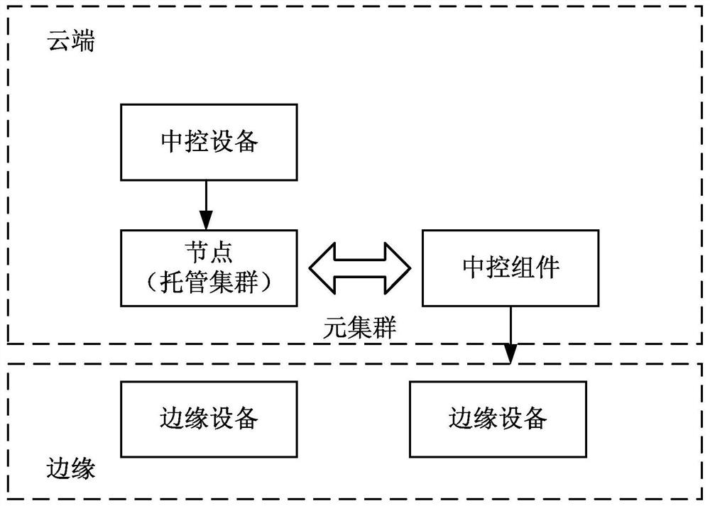
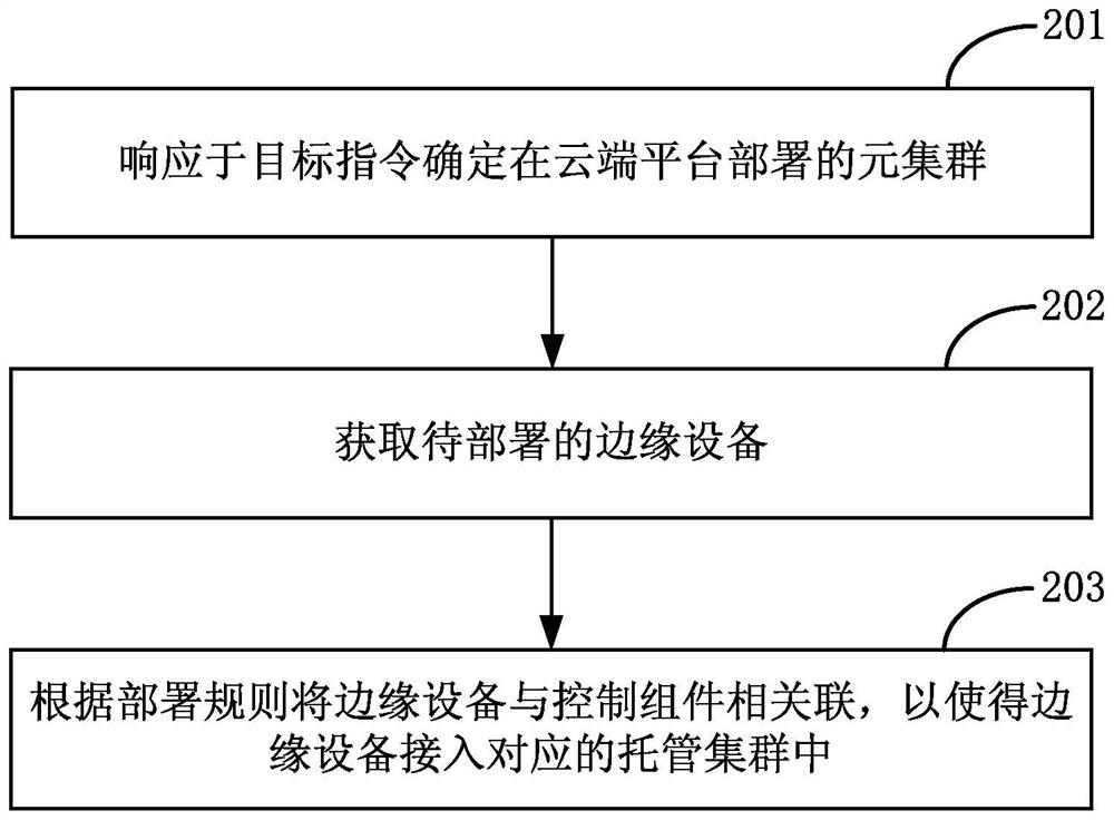
[0089] The embodiment of the present application provides a method for managing edge devices and related devices, which can be applied to systems or programs that include management functions of edge devices in terminal devices. The cluster includes a central control device and at least one associated hosting cluster, the central control device is used to issue target instructions to the hosting cluster, and at least one control component is configured in the hosting cluster; then obtain the edge device to be deployed; then the edge device It is associated with the control component to deploy the edge service corresponding to the target command on the edge device. In this way, the process of rapidly expanding and managing edge devices is realized. Since edge devices are managed through the control components in the hosting cluster, there is no need to redeploy the upper-layer meta-cluster framework during the cluster expansion process, which improves the expansion efficiency of edge devices.
[0090] The terms "first", "second", "third", "fourth", etc. (if any) in the specification and claims of the present application and the above drawings are used to distinguish similar objects, and not necessarily Used to describe a specific sequence or sequence. It is to be understood that the data so used are interchangeable under appropriate circumstances such that the embodiments of the application described herein, for example, can be practiced in sequences other than those illustrated or described herein. Furthermore, the terms "comprising" and "corresponding to" and any variations thereof, are intended to cover a non-exclusive inclusion, for example, a process, method, system, product or device comprising a sequence of steps or elements need not be limited to the expressly listed Instead, other steps or elements not explicitly listed or inherent to the process, method, product or apparatus may be included.
[0091] First, some nouns that may appear in the embodiments of the present application are explained.
[0092] kubernetes: also known as k8s, is a distributed cluster management system. On each node (node), an executive program (worker) must be run to manage the life cycle of the container. The executive program is kubelet.
[0093] kubelet: The main function is to regularly obtain the expected state of the microservice process on the node from somewhere (what container is running, the number of copies running, how to configure the network or storage, etc.), and call the corresponding container platform interface to achieve this state.
[0094] Pod: The smallest/simplest basic unit created or deployed by kubernetes. A Pod represents a microservice process running on the cluster, and a microservice process encapsulates an edge container that provides microservice applications (there can also be multiple edge containers ), storage resources, a separate network IP, and management policy options that control how containers run.
[0095] kube-proxy: An interface proxy used to manage the access entry of service objects (Service). The proxy objects include access from microservice processes in the cluster to service objects and access to service objects outside the cluster.
[0096] Edge computing refers to an open platform that integrates network, computing, storage, and application core capabilities on the side close to the source of objects or data. The edge side of the network can be any functional entity from the data source to the cloud computing center. These entities are equipped with an edge computing platform that integrates network, computing, storage, and application core capabilities to provide end users with real-time, dynamic, and intelligent service computing. .
[0097] Generally, edge computing is managed in the form of clusters. A single cluster can only manage devices of a certain scale due to performance limitations. If the number of devices exceeds the upper limit of the scale, one or more clusters need to be created to meet the larger scale of edge devices.
[0098] However, to create a cluster, you need to prepare the machines on the cluster control plane, and then deploy the cluster, that is, deploy from the perspective of the overall architecture of the cluster. The deployment process is cumbersome and costly, which affects the expansion efficiency of edge devices.
[0099] In order to solve the above problems, this application proposes a management method for edge devices, which is applied to figure 1 shown in the system framework for the management of edge devices, such as figure 1 As shown, it is a system architecture diagram of edge device management provided by the embodiment of the present application. Specifically, the system architecture is divided into the cluster management process of the cloud control plane component (central control device master) and the edge end edge Device access deployment process. This application mainly uses the container technology docker and the container orchestration tool technology kubernetes (hereinafter referred to as k8s). Among them, the cloud mainly deploys the master-related components of kubernetes, and the cloud control plane components are divided into meta-clusters and managed clusters.
[0100] Specifically, the meta-cluster is a complete and independent k8s cluster, including k8s master nodes and k8s node nodes. The node nodes of k8s can be quickly expanded and added horizontally. The node node runs the master component hosting the k8s cluster, where the node node can be a physical host or a virtual machine.
[0101] The managed cluster is the node used by the managed k8s cluster to register and manage edge devices. The managed k8s cluster mainly deploys the components of the master part, including kube-apiserver, kube-controller-manager, kube-scheduler, etcd and other components. The master of the managed cluster runs on the node node of the meta-cluster in the form of a container (pod).
[0102] Commands are issued through the central control device in the cloud, so that the managed k8s business cluster can be created and managed through the k8s meta-cluster (that is, the kube on kube method), so that the number of managed k8s business clusters can be quickly increased to increase the cloud control node, and the edge The device is registered to the managed service cluster control node to realize cloud management of edge devices.
[0103] It can be understood that a managed cluster control node can manage a certain scale of edge devices, and when more managed cluster control nodes are added, a larger scale of edge devices can be quickly managed.
[0104]In this embodiment, the server can be an independent physical server, or a server cluster or a distributed system composed of multiple physical servers, and can also provide cloud services, cloud databases, cloud computing, cloud functions, cloud storage, and network services , cloud communications, middleware services, domain name services, security services, CDN, and cloud servers for basic cloud computing services such as big data and artificial intelligence platforms. The terminal may be a smart phone, a tablet computer, a laptop computer, a desktop computer, a smart speaker, a smart watch, etc., but is not limited thereto. Terminals and servers can be connected directly or indirectly through wired or wireless communication, and terminals and servers can be connected to form a blockchain network, which is not limited in this application.
[0105] It can be understood that the method provided by this application can be written as a program, as a processing logic in the hardware system, or as a management device for edge devices, and can be implemented in an integrated or external manner. processing logic. As an implementation, the management device of the edge device determines the meta-cluster deployed on the cloud platform in response to the target instruction, the meta-cluster includes the central control device and at least one associated hosting cluster, and the central control device is used to provide Issue the target instruction, configure at least one control component in the hosting cluster; then obtain the edge device to be deployed; then associate the edge device with the control component to deploy the edge service corresponding to the target instruction on the edge device. In this way, the process of rapidly expanding and managing edge devices is realized. Since edge devices are managed through the control components in the hosting cluster, there is no need to redeploy the upper-layer meta-cluster framework during the cluster expansion process, which improves the expansion efficiency of edge devices.
[0106] The solutions provided in the embodiments of the present application relate to cloud technology, and are specifically described through the following embodiments:
[0107] Combined with the above process architecture, the following will introduce the management method of edge devices in this application, please refer to figure 2 , figure 2 It is a flowchart of an edge device management method provided by the embodiment of the present application. The management method may be executed by a cloud device or a server. The embodiment of the present application includes at least the following steps:
[0108] 201. Determine a meta-cluster deployed on a cloud platform in response to a target instruction.
[0109] In this embodiment, the meta-cluster includes a central control device (control plane component) and at least one associated hosting cluster, wherein the central control device is used to issue target instructions to the hosting cluster, and at least one control plane component is configured in the hosting cluster components.
[0110] It can be understood that this application is described with one meta-cluster deployed on the cloud platform, and in an actual scenario, the cloud platform may contain multiple parallel meta-clusters.
[0111] Specifically, the target instruction may be an instruction to add an edge device in the meta-cluster, may also be an instruction to delete an edge device, or may be a specific service instruction, which is not limited here.
[0112] Compared with the way of managing edge devices in the cloud cluster dimension in the prior art, this application is equivalent to dividing the cloud cluster, and adjusting the single-layer control of the control device to the node to include meta-cluster (control device control) and hosting cluster The hierarchical structure of (node control) facilitates the management of edge devices. For example, in the k8s scenario, the single-layer control of nodes by k8smaster is adjusted to a hierarchical structure of meta-clusters and managed clusters (master components are configured in nodes).
[0113] Specifically, for the process of determining the meta-cluster and its associated managed cluster, it may be created. That is, first set the area label for the node unit in the initial cluster in response to the target command; then call the target service within the scope of the area label to determine the target interface in the node unit, the target service is etcd service; then based on the target interface in the node Create a control component in the unit to determine it as a managed cluster; and then determine the central control device associated with the managed cluster to determine the meta-cluster.
[0114] Among them, etcd is a distributed and reliable key-value storage distributed system. It is not only used for storage, but also provides shared configuration and service discovery. Service discovery (Service Discovery) can find each other and establish a connection in the process or service in the same distributed cluster.
[0115] Specifically, etcd uses the raft protocol to maintain the consistency of the state of each node in the cluster. The etcd service is a distributed system, which consists of multiple nodes communicating with each other to form an overall external service. Each node stores complete data, and the data maintained by each node is guaranteed to be consistent through the raft protocol, that is, to ensure that the managed cluster corresponds to Node data is consistent. In addition, each node in the etcd service maintains a state machine, and there is at most one valid master node at any time. The master node handles all write operations from the client, and through the Raft protocol, it is guaranteed that the changes to the state machine by the write operations will be reliably synchronized to other nodes, thereby ensuring that the data of the nodes corresponding to the managed cluster is consistent.
[0116] Optionally, during the process of creating a managed cluster based on the node nodes of the meta-cluster, a review process can also be performed, that is, the control component is created in the node unit based on the target interface, and the detection process is invoked; if the detection process indicates that the control component is in the node unit If the online service is normal, it is determined to be a managed cluster. This ensures the credibility of the hosting cluster.
[0117] 202. Obtain an edge device to be deployed.
[0118] In this embodiment, the edge device to be deployed may be selected from multiple candidate edge devices, that is, only candidate edge devices that are successfully registered on the cloud platform can be deployed. Specifically, first determine a plurality of candidate edge devices; then call the node registration interface of the cloud platform to obtain the registration parameters of the candidate edge devices; and then determine the edge devices to be deployed based on the registration parameters. Wherein, the registration parameters may include device performance parameters such as load status and service duration of the edge device, and may also include geographical parameters such as device distribution location and connection status.
[0119] Optionally, in order to facilitate the management of edge devices by the managed cluster, you can select the ones with similar locations; that is, first determine the location information of the candidate edge device according to the registration parameters; then determine the corresponding managed cluster based on the location information; thus, node Register to identify an edge device to be deployed. Through the screening of location information, the timeliness of managing edge devices by managed clusters is improved.
[0120] Optionally, since the meta-cluster is associated with multiple managed clusters, when allocating managed clusters for edge devices, the load of the managed clusters, that is, the number of managed edge devices, may be considered. Specifically, the load information of the hosting cluster is obtained first; if the load information satisfies the preset condition, node registration is performed in the hosting cluster to determine it as an edge device to be deployed. For example, the preset condition is that the load rate is less than 60% or not fully loaded, and the specific value setting depends on the actual scene.
[0121] Optionally, when the load information does not meet the preset conditions, a candidate managed cluster can be created based on the edge device to be deployed. The candidate managed cluster can be another managed cluster associated in the meta-cluster, or it can be newly created in the meta-cluster A managed cluster that improves the accuracy of edge device management.
[0122] 203. Associate the edge device with the control component according to the deployment rule, so that the edge device is connected to the corresponding hosting cluster.
[0123] In this embodiment, through the configuration of the above-mentioned meta-cluster and hosting cluster, the edge device is associated with the corresponding hosting cluster, that is, the hosting cluster is used to deploy the edge service corresponding to the target instruction on the edge device, so that the edge in the meta-cluster can be obtained The service information realizes the horizontal expansion of the cluster scale of the cloud platform. This horizontal expansion is also called horizontal expansion, and more nodes are used to support a larger number of requests. In addition, the deployment rules are used to ensure that the edge devices can be fully accessed after they are connected to the hosting cluster. The rules used, specifically, the deployment rules can be determined based on the location information or business information corresponding to the edge service; for example, if the edge service corresponds to business A, then determine the edge device that is suitable for business A, assuming that business A is in hosting cluster 1 Medium (different hosting clusters can be set differently) camera equipment with a resolution of at least 4K (requirements for business information), then in the process of determining the edge device, the resolution can be screened; or the edge service corresponds to area B service, associate the hosting cluster corresponding to area B with the edge device whose location information is close to area B, so as to improve the response efficiency between the edge and the cloud; it can be understood that the setting of the above deployment rules can be the One or more combinations of the above examples can also be used for manual access by relevant personnel, that is, deployment rules correspond to manual access, or automatic access, that is, deployment rules correspond to free access. The specific method It depends on the actual scene, and there is no limitation here.
[0124] Specifically, for the configuration process of delivering the edge service to the edge device, the image service corresponding to the edge service can be uploaded to the image warehouse first, where the image warehouse is used to store the Docker image, and the Docker image is used to deploy the container service. Each image There is a specific unique identifier, such as Registry address identified as a mirror + mirror name + mirror Tag; then mirror services are deployed in the mirror warehouse; and based on the mirror services, the edge services corresponding to the target instructions are deployed on the edge devices, thus ensuring the edge services. Traceability improves the stability of edge service configuration.
[0125] In addition, during the mirror service configuration process, the deployment parameters corresponding to the mirror service can be determined; and then the deployment space can be determined according to the deployment parameters for deployment in the mirror warehouse. For example, classify image services to facilitate service statistics.
[0126] Optionally, after the edge service is deployed, a deployment test command can be initiated; then based on the deployment test command, the edge service is tested in the edge device to obtain the test result; if the test result meets the test conditions, the deployment of the edge service in the edge device is completed. Deployment ensures the stability and reliability of edge service deployment.
[0127] This application can deploy and expand clusters conveniently and quickly, and increase the number of managed edge devices. Assuming that there are 6 central control devices with 48 cores and 64G resources, in the case of the existing technical solution, up to 6000 edge devices can be managed. However, through this application, the six devices can manage 120,000 edge devices. In the case of the same central control equipment resources, the scale of equipment managed by this application is 20 times that of the prior art. Compared with the prior art, the technology of the present application has strong cluster scalability, and the cluster expansion efficiency is calculated in seconds, while the cluster expansion efficiency of the prior art is calculated in hours or days.
[0128] In combination with the above-mentioned embodiments, it can be seen that the meta-cluster deployed on the cloud platform is determined in response to the target instruction, and the meta-cluster includes a central control device and at least one associated managed cluster, and the central control device is used to issue a target command to the managed cluster, and the managed At least one control component is configured in the cluster; then the edge device to be deployed is obtained; and the edge device is associated with the control component, so as to deploy the edge service corresponding to the target instruction on the edge device. In this way, the process of rapidly expanding and managing edge devices is realized. Since edge devices are managed through the control components in the hosting cluster, there is no need to redeploy the upper-layer meta-cluster framework during the cluster expansion process, which improves the expansion efficiency of edge devices.
[0129] The above-mentioned embodiment introduces the deployment process of the edge node on the cloud platform, and the prior configuration of the cloud platform will be described below. The pre-configuration of the cloud platform includes three steps: deploying k8s meta-cluster and business hosting cluster; registering and checking edge nodes, deploying and checking edge services, which are explained below.
[0130] For the process of deploying k8s meta-cluster and managed cluster, see image 3 , image 3 The flow chart of another edge device management method provided by the embodiment of the present application includes the following steps:
[0131] 301. Deploy a meta-cluster.
[0132]In this embodiment, the meta-cluster is the k8s meta-cluster, including the k8s master node and the k8s node node; among them, the k8s node node can be quickly expanded and added horizontally, and the master component hosting the k8s cluster runs on the node node. The master component is ready to use for edge device management.
[0133] Specifically, the deployment of the meta-cluster can be set according to all the node nodes associated with the current k8s master node, or some of them can be selected, for example: initiate resource detection on the node node to obtain the working information of the node node (load status , availability, etc.), so as to select the node nodes whose status meets the conditions for deployment.
[0134] 302. Label the nodes of the meta-cluster with regions.
[0135] In this embodiment, setting an area label for the node of the meta-cluster is equivalent to an identifier set for the control component (master component) in the hosting cluster.
[0136] Specifically, the setting of the area identification can be divided according to the specific business. For example, for the control component responsible for business A, mark the mark 1, mark the control component responsible for business B with mark 2, and correspondingly be responsible for its business path Set the corresponding identifier for the associated device; the setting of the regional identifier can also be divided according to the geographical range. Since the deployment of the edge device is regional, the master component can be set in different geographical locations, that is, the node node is deployed. This ensures the convenience of the edge management process.
[0137] It can be understood that the area ID can be used as a reference in the management process of edge devices, that is, in the actual management process of edge devices, the device deployment can not be based on the area ID. This is to avoid sudden device failure. scheduling.
[0138] 303. Create a target service of the managed cluster.
[0139] In this embodiment, the target service is to create an etcd service hosting k8s. etcd is a distributed service system for distributed and reliable key-value storage. The etcd service is not only used for storage, but also provides shared configuration and service discovery.
[0140] Specifically, the storage served in etcd is a flat binary key space, and the key space has a lexicographic index for keys (byte strings), so the cost of range queries is low. Among them, the key space maintains multiple revisions (revisions), and each atomic change operation (a transaction can be composed of multiple sub-operations) will generate a new revision. Revisions are monotonically increasing throughout the lifetime of the cluster. Revisions also support indexes, so revision-based range scans are also efficient. The compression operation needs to specify a revision number, and revisions smaller than it will be removed to ensure the accuracy of the compression.
[0141] 304. Create a control component of the hosting cluster on the node of the meta-cluster.
[0142] In this embodiment, the process of creating the control component of the hosting cluster is to deploy the master component on the node node, so that the node node has the ability to manage edge devices.
[0143] 305. Configure an access interface address of the hosting cluster.
[0144] In this embodiment, after the master component is deployed on the node node, multiple edge devices can be managed. In a possible scenario, a managed cluster (including multiple node nodes deployed with the master component) can manage 5000 edge devices equipment. Therefore, it is necessary to configure corresponding multi-interfaces for the hosting cluster, and store the access interface addresses through the etcd service and associate corresponding devices to ensure the independence of services between master components.
[0145] 306. Check whether the managed cluster is available.
[0146] In this embodiment, the checking process can query the cluster health check interface by invoking the etcd service to check the interface and test related services, so as to check whether the deployment of the hosting cluster is normal.
[0147] 307. Return service deployment failure and error.
[0148] In this embodiment, if the check on the hosting cluster in step 306 indicates that the hosting cluster is unavailable, service deployment failure and an error report will be returned, so as to facilitate deployment adjustments.
[0149] 308. The managed cluster is created.
[0150] In this embodiment, if the service is normal, call the interface for deploying the hosting cluster, deploy the k8s hosting cluster master service, and run it on the node node of the k8s meta-cluster. Then configure the access address of the hosted k8s system interface (api), which means that the deployment of the meta-cluster and managed cluster is completed.
[0151] For the process of registering and checking edge nodes, such as Figure 4 as shown, Figure 4 The flow chart of another edge device management method provided by the embodiment of the present application includes the following steps:
[0152] 401. Register one or more edge devices.
[0153] In this embodiment, in order to ensure the credibility of the edge device, the edge device that accesses the hosting cluster needs to be registered on the cloud platform.
[0154] 402. Fill in the edge device registration parameters.
[0155] In this embodiment, the registration parameters of the edge device include identification information (device number, authentication number, etc.), location information (IP address, home location, etc.) and function information (load capacity, availability status, etc.) of the edge device.
[0156] 403. Check whether the node meets the registration condition.
[0157] In this embodiment, the judgment of the registration conditions can be performed according to the registration parameters, that is, to verify one or more of the identification information, location information or function information, such as checking the credibility of the authentication number; changing the attribution Frequency; whether it is the best load state, etc.
[0158] 404. Return registration failure and error.
[0159] In this embodiment, if the registration information of the edge device does not meet the registration condition in step 403, it will feed back the registration failure and the specific reason for the failure to the cloud platform, that is, the process of reporting an error.
[0160] It can be understood that after the error is reported, the corresponding edge device can be recorded, and when the device registers again, a reminder is given to further check the dimensions indicated by the error report.
[0161] 405. Automatically select a hosting cluster.
[0162] In this embodiment, if the registration condition is met, the managed cluster is automatically selected. Specifically, the automatic selection process may be based on location information, for example, the managed cluster that belongs to the same area as the edge device is automatically selected; the automatic selection process may be based on For business, for example, the edge device is automatically selected to belong to the hosting cluster of service A, thereby saving the subsequent process of grouping edge devices.
[0163] 406. Determine whether the number of nodes in the hosting cluster reaches the upper limit.
[0164] In this embodiment, considering the capacity of the hosting cluster and the efficiency of managing edge devices, the number of nodes (edge devices) managed in the hosting cluster can be upper-limited. Specifically, the upper limit can be the upper limit of the load, that is, the most accessed The number of nodes; the upper limit can also be a value set by the real-time resource load of different hosting clusters. For example, the busy hour threshold is 80% of the load upper limit, and the idle time threshold is 60% of the load upper limit. The specific value setting depends on the actual It depends on the scenario, thus ensuring the stability of the edge device managed by the hosting cluster.
[0165] 407. Create a hosting cluster.
[0166] In this embodiment, if the upper limit is reached, a managed cluster is created. Specifically, the created managed cluster can be repeated image 3 The steps of the shown embodiment can also be optional image 3 In the steps of the illustrated embodiment, the hosting cluster of the edge device is not connected or the hosting cluster of the upper limit is not reached.
[0167] It can be understood that, for the creation of a new hosting cluster, it is associated with the registered edge device during the creation process, that is, it is associated with the edge device immediately after the hosting cluster is created, so as to improve the access efficiency of the edge device.
[0168] 408. Check whether the registration of the node is successful.
[0169] In this embodiment, after associating the node corresponding to the edge device with the hosting cluster, another node verification is required to ensure the credibility of the connection between the edge device and the hosting cluster. Specifically, it can be checked through the process of sending identification information, that is, the managed cluster sends a check command to the associated edge device, and the edge device will respond to the check command, and determine whether the check node is successfully registered according to the response.
[0170] 409. Return node registration failure and error reporting.
[0171] In this embodiment, according to the check instruction response in step 408, if the hosting cluster does not receive a response from the edge device, it means that the registration of the edge device has failed, and relevant information of the edge device is generated for inspection.
[0172] 410. The edge node registers successfully.
[0173] In this embodiment, according to the check instruction response in step 408, if the hosting cluster receives the response from the edge device, it means that the edge device is registered successfully, and the edge device has been deployed as an edge node in the hosting cluster.
[0174] Further, for the process of deploying and checking edge services, see Figure 5 , Figure 5 The flow chart of another edge device management method provided by the embodiment of the present application includes the following steps:
[0175] 501. Upload the edge service image to the mirror warehouse.
[0176] In this embodiment, the process of the edge service is the process of delivering the service through the cloud platform. In order to ensure the consistency of the service, the edge service image can be uploaded to the mirror warehouse first. Specifically, multiple namespaces may be included in the mirror warehouse, that is, different edge services are configured in different namespaces to achieve parallelism of multiple services.
[0177] 502. Deploy the edge mirroring service.
[0178] In this embodiment, the process of deploying the edge mirroring service is to call the edge service deployment interface, and deploy the edge service through the service mirroring.
[0179] 503. Fill in the deployment parameters of the edge service.
[0180] In this embodiment, the deployment parameters may include required resource parameters and regional parameters. Specifically, the resource parameters are related parameters used to indicate the hardware or software resources required for the edge service operation process, such as: the amount of occupied resources, the number of required devices etc.; and the region parameter is used to indicate the objects targeted by the edge service, and then select the edge device that is closer to these objects.
[0181] 504. Select an edge device meeting the deployment parameter condition.
[0182]In this embodiment, the fulfillment of the deployment parameter condition refers to the fulfillment of the condition of the resource parameter or the geographical parameter dimension, for example, selecting an edge device with storage capacity of 1G, or selecting an edge device within range A.
[0183] 505. The cloud platform automatically deploys the edge service to the corresponding edge device.
[0184] In this embodiment, edge services can be quickly deployed to corresponding edge devices through the selection of edge devices by the hosting cluster and the determination of corresponding interfaces.
[0185] 506. Check whether the edge service is deployed successfully.
[0186] In this embodiment, checking the deployment status of the edge service may call the edge service health check interface to check whether the edge service is deployed successfully.
[0187] 507. Return service deployment failure and error.
[0188] In this embodiment, if the health check indicates an abnormality, it returns that the service deployment failed, and records the corresponding edge service for easy checking.
[0189] 508. Returning that the deployment is successful.
[0190] In this embodiment, if the health check is normal, the deployment of the edge service is successful.
[0191] After performing the configuration process of the above cloud platform and edge nodes, the following can be obtained: Image 6 Shown in the system architecture diagram, Image 6 It is a system architecture diagram of another edge device management method provided by the embodiment of the present application. It is mainly divided into cloud platform (cloud) central control equipment (meta k8s master) and edge terminal (edge) edge equipment (node). Among them, three deployment cluster nodes 1-3 (node1-3) are associated in the meta cluster (meta) corresponding to the central control device, and four control components A-D (k8s master pod A-D), and each control component is associated with four edge devices at the edge end. The specific number of devices depends on the actual scenario, and this is just an example.
[0192] Specifically, for Image 6 The deployment process of the edge service involves the selection process of the control components in the managed cluster (node) and the edge device. In the following embodiments, the managed cluster is expressed as a node.
[0193] In a possible scenario, the edge service contains sub-services with 4 threads. At this time, the service needs to be delivered. First, the central control device traverses the load status of the nodes in the meta-cluster, and determines the nodes 1-3 Assign the above sub-services; next, the node traverses the load status of the control components managed by itself, and selects the control components that meet the load conditions to execute sub-services, for example: idle components; as shown in the figure, the load status of node 1 is approaching saturation , so only the control component A is called to carry out the load of the sub-service; the load status of node 2 is free, so the control component B and control component C are called to carry out the load of the sub-service; the load state of node 3 is approaching saturation, so the control component D is called to carry out the sub-service load; thus, based on the determination of the above control components, the control components deliver sub-services according to the edge devices they manage.
[0194] It can be understood that the delivery of sub-services by the control component can be delivered to edge devices within the target range, that is, the area label in the registration process of edge devices is used to deliver sub-services, thereby improving the efficiency of service delivery and accuracy.
[0195] It is understandable that the cloud central control device uses a k8s meta-cluster to create and manage multiple k8s managed clusters; the node nodes of the meta-cluster can be quickly expanded horizontally, and the number of managed clusters can also be quickly created and expanded; a managed cluster can be up to Manage 5,000 edge devices, so that the number of managed edge devices can be quickly expanded by quickly creating and managing multiple hosting clusters.
[0196] In one possible scenario, this application can be applied to various edge computing scenarios, for example, it can be applied to manage edge devices such as various cameras on highways, video surveillance in communities, and edge devices such as various face recognition devices. , Various PCDN and CDN edge devices.
[0197] The following describes the configuration scenarios of cameras on highways, such as Figure 7 as shown, Figure 7 A flow chart of another edge device management method provided by the embodiment of this application; including but not limited to the following steps:
[0198] 701. Acquire the edge device corresponding to the newly added road.
[0199] In this embodiment, it is applied to the expansion scenario of road cameras. Since the road cameras are deployed in a large number and are widely distributed, the edge device management method provided by this application can be used to perform a rapid device expansion process.
[0200] Specifically, the edge device corresponding to the newly added road is the camera device added to the newly added road. In order to facilitate the management of the camera device, it can be registered in the cloud and associated with the control component in the managed cluster in this application. Wherein, the hosting cluster may be set according to the area label, for example, the hosting cluster configured for roads in area A, so as to improve the compatibility between the camera device and the hosting cluster during the registration process in the cloud.
[0201] In this embodiment, the registration process of the edge device refers to Figure 4 The steps of the illustrated embodiment are not repeated here.
[0202] 702. Deploy the edge device based on the cloud platform.
[0203] In this embodiment, the process of edge device deployment refers to image 3 or Figure 5 The process of associating the middle edge device with the control component will not be repeated here.
[0204] 703. Deploy the task of the area corresponding to the newly added road to the edge device.
[0205] In this embodiment, since the newly added road and its configured edge devices have certain geographic location characteristics, a hosting cluster in a corresponding area can be configured nearby for management, thereby improving management efficiency.
[0206] On the other hand, through the central control device corresponding to the meta-cluster, the task execution information of each managed cluster, that is, the camera information, for example: vehicle violation information; specifically, the vehicle violation information can be collected in the managed cluster for camera information And processed and uploaded to the central control device, that is, the violation information collected by the central control device is a collection of violation information in each area. Compared with the management process of each node corresponding to the edge device, the violation information collected by this application is more accurate. It is fast and comprehensive, and because the process of organizing regional information is delegated to the hosting cluster, the resources consumed by the central control equipment to process data are reduced, and it can be applied to the management of a wider range of cameras.
[0207] Through the management method of the edge device in this application, it can be fully connected to the camera management system of the expressway, and the overall management efficiency will not be affected by the increasing number of cameras, and it is convenient for large-scale camera access to the cloud platform, and carry out the management process of corresponding tasks.
[0208] In order to better implement the above solutions of the embodiments of the present application, related devices for implementing the above solutions are also provided below. see Figure 8 , Figure 8 It is a schematic structural diagram of an edge device management device provided in an embodiment of the present application. The management device 800 includes:
[0209] The determining unit 801 is configured to determine a meta-cluster deployed on the cloud platform in response to a target instruction, the meta-cluster includes a central control device and at least one associated hosting cluster, and the central control device is used to download to the hosting cluster sending the target instruction, at least one control component is configured in the managed cluster;
[0210] An acquisition unit 802, configured to acquire an edge device to be deployed;
[0211] The management unit 803 is configured to associate the edge device with the control component according to a deployment rule, so that the edge device is connected to the corresponding hosting cluster, and the hosting cluster is used to deploy The edge service corresponding to the target instruction, the deployment rule is determined based on the location information or service information corresponding to the edge service.
[0212] Optionally, in some possible implementation manners of the present application, the determining unit 801 is specifically configured to set area labels for node units in the initial cluster in response to the target instruction;
[0213] The determining unit 801 is specifically configured to call a target service within the scope of the area label to determine the target interface in the node unit;
[0214] The determining unit 801 is specifically configured to create the control component in the node unit based on the target interface, so as to determine it as the managed cluster;
[0215] The determining unit 801 is specifically configured to determine the central control device associated with the hosting cluster, so as to determine the meta-cluster.
[0216] Optionally, in some possible implementation manners of the present application, the determining unit 801 is specifically configured to create the control component in the node unit based on the target interface, and invoke a detection process;
[0217] The determining unit 801 is specifically configured to determine that it is the hosting cluster if the detection process indicates that the control component is running normally on the node unit.
[0218] Optionally, in some possible implementation manners of the present application, the obtaining unit 802 is specifically configured to determine a plurality of candidate edge devices;
[0219] The obtaining unit 802 is specifically configured to call a node registration interface of the cloud platform to obtain registration parameters of the candidate edge device;
[0220] The acquiring unit 802 is specifically configured to determine the edge device to be deployed based on the registration parameter.
[0221] Optionally, in some possible implementation manners of the present application, the obtaining unit 802 is specifically configured to determine the location information of the candidate edge device by the registration parameter;
[0222] The obtaining unit 802 is specifically configured to determine the corresponding hosting cluster based on the location information;
[0223] The obtaining unit 802 is specifically configured to perform node registration in the hosting cluster, so as to determine the edge device to be deployed.
[0224] Optionally, in some possible implementation manners of the present application, the obtaining unit 802 is specifically configured to obtain the load information of the hosting cluster;
[0225] The obtaining unit 802 is specifically configured to, if the load information satisfies a preset condition, perform node registration in the hosting cluster to determine the edge device to be deployed.
[0226] Optionally, in some possible implementation manners of the present application, the acquiring unit 802 is specifically configured to create a candidate hosting cluster based on the edge device to be deployed if the load information does not satisfy the preset condition.
[0227] Optionally, in some possible implementations of the present application, the management unit 803 is specifically configured to associate the edge device with the control component according to deployment rules, and upload the image service corresponding to the edge service to to the mirror warehouse;
[0228] The management unit 803 is specifically configured to deploy the mirror service in the mirror warehouse;
[0229] The management unit 803 is specifically configured to deploy the edge service corresponding to the target instruction on the edge device based on the image service.
[0230] Optionally, in some possible implementation manners of the present application, the management unit 803 is specifically configured to determine deployment parameters corresponding to the image service;
[0231] The management unit 803 is specifically configured to determine a deployment space according to the deployment parameters for deployment in the mirror repository.
[0232] Optionally, in some possible implementations of the present application, the management unit 803 is specifically configured to initiate a deployment test instruction;
[0233] The management unit 803 is specifically configured to test the edge service in the edge device based on the deployment test instruction to obtain a test result;
[0234] The management unit 803 is specifically configured to complete the deployment of the edge service in the edge device if the test result meets the test condition.
[0235] The meta-cluster deployed on the cloud platform is determined by responding to the target instruction. The meta-cluster includes a central control device and at least one associated managed cluster. The central control device is used to issue a target command to the managed cluster. At least one of the managed clusters is configured The control component; then obtain the edge device to be deployed; and then associate the edge device with the control component, so as to deploy the edge service corresponding to the target instruction on the edge device. In this way, the process of rapidly expanding and managing edge devices is realized. Since edge devices are managed through the control components in the hosting cluster, there is no need to redeploy the upper-layer meta-cluster framework during the cluster expansion process, which improves the expansion efficiency of edge devices.
[0236] The embodiment of this application also provides a server, please refer to Figure 9 , Figure 9 It is a schematic structural diagram of a server provided in the embodiment of the present application. The server 900 may have relatively large differences due to different configurations or performances, and may include one or more central processing units (central processing units, CPU) 922 (for example, one or more processors) and memory 932, and one or more storage media 930 (such as one or more mass storage devices) for storing application programs 942 or data 944. Wherein, the memory 932 and the storage medium 930 may be temporary storage or persistent storage. The program stored in the storage medium 930 may include one or more modules (not shown in the figure), and each module may include a series of instruction operations on the server. Furthermore, the central processing unit 922 may be configured to communicate with the storage medium 930 , and execute a series of instruction operations in the storage medium 930 on the server 900 .
[0237] The server 900 can also include one or more power supplies 926, one or more wired or wireless network interfaces 950, one or more input and output interfaces 958, and/or, one or more operating systems 941, such as Windows Server™, Mac OS XTM, UnixTM, LinuxTM, FreeBSDTM, etc.
[0238] The steps performed by the management device in the above embodiments may be based on the Figure 9 The server structure shown.
[0239] The embodiment of the present application also provides a computer-readable storage medium, the computer-readable storage medium stores the management instructions of the edge device, and when it runs on the computer, the computer executes the aforementioned Figure 1 to Figure 7 The steps performed by the management apparatus of the edge device in the method described in the illustrated embodiment.
[0240] The embodiment of the present application also provides a computer program product including management instructions of the edge device, when it runs on the computer, the computer executes the above-mentioned Figure 1 to Figure 7 The steps performed by the management apparatus of the edge device in the method described in the illustrated embodiment.
[0241] The embodiment of the present application also provides a management system for edge devices, and the management system for edge devices may include Figure 8 The management means of the edge device in the described embodiments, or Figure 9 described server.
[0242] In a possible scenario, the network resource management method in this application is applied to a blockchain device, that is, the authoritative DNS, LDNS or terminal is a blockchain device, and the blockchain device is a blockchain device The nodes are described below in conjunction with the accompanying drawings; see Figure 10A In the data sharing system shown, the data sharing system 1000 refers to a system for sharing data between nodes, the data sharing system may include multiple nodes 1001, and the multiple nodes 1001 may refer to each node in the data sharing system client. Each node 1001 can receive input information during normal operation, and maintain the shared data in the data sharing system based on the received input information. In order to ensure information intercommunication in the data sharing system, there may be an information connection between each node in the data sharing system, and information transmission may be performed between nodes through the above information connection. For example, when any node in the data sharing system receives input information, other nodes in the data sharing system will obtain the input information according to the consensus algorithm, and store the input information as data in the shared data, so that the data in the data sharing system The data stored on all nodes are consistent.
[0243] For each node in the data sharing system, there is a node ID corresponding to it, and each node in the data sharing system can store the node IDs of other nodes in the data sharing system, so that later, according to the node IDs of other nodes, Broadcast the generated blocks to other nodes in the data sharing system. Each node can maintain a node ID list as shown in the following table, and store the node name and node ID in the node ID list. Wherein, the node identifier may be an IP (Internet Protocol, a protocol for interconnecting networks) address and any other information that can be used to identify the node. Table 1 only uses the IP address as an example for illustration.
[0244] Table 1 Correspondence between node names and node identifiers
[0245] node name Node ID node 1 117.114.151.174 node 2 117.116.189.145 … … Node N 119.123.789.258
[0246] Every node in the data sharing system stores an identical blockchain. A blockchain consists of multiple blocks, see Figure 10B , the blockchain is composed of multiple blocks, the genesis block includes a block header and a block body, the block header stores input information characteristic value, version number, timestamp and difficulty value, and the block body stores input information; The next block of the genesis block takes the genesis block as the parent block, and the next block also includes the block header and the block body. The block header stores the input information characteristic value of the current block and the block header characteristics of the parent block. value, version number, timestamp and difficulty value, and so on, so that the block data stored in each block in the blockchain is associated with the block data stored in the parent block, ensuring that Security of Entered Information.
[0247] When generating individual blocks in the blockchain, see Figure 10C , when the node where the blockchain is located receives the input information, it verifies the input information. After the verification is completed, the input information is stored in the memory pool, and the hash tree used to record the input information is updated; after that, Update the update timestamp to the time when the input information is received, try different random numbers, and perform eigenvalue calculations multiple times, so that the calculated eigenvalues can satisfy the following formula:
[0248] SHA256(SHA256(version+prev_hash+merkle_root+ntime+nbits+x))
[0249] Among them, SHA256 is the eigenvalue algorithm used to calculate the eigenvalue; version (version number) is the version information of the relevant block protocol in the blockchain; prev_hash is the block header eigenvalue of the parent block of the current block; merkle_root is the input information ntime is the update time of the update timestamp; nbits is the current difficulty, which is a fixed value for a period of time, and will be determined again after a fixed period of time; x is a random number; TARGET is the threshold of the feature value, the feature The value threshold can be determined according to nbits.
[0250] In this way, when the random number satisfying the above formula is calculated, the information can be stored correspondingly, the block header and block body are generated, and the current block is obtained. Subsequently, according to the node identification of other nodes in the data sharing system, the node where the blockchain is located sends the newly generated blocks to other nodes in the data sharing system where it is located, and the other nodes verify the newly generated blocks , and add the newly generated block to its stored blockchain after the verification is completed.
[0251] Those skilled in the art can clearly understand that for the convenience and brevity of the description, the specific working process of the above-described system, device and unit can refer to the corresponding process in the foregoing method embodiment, which will not be repeated here.
[0252] In the several embodiments provided in this application, it should be understood that the disclosed system, device and method can be implemented in other ways. For example, the device embodiments described above are only illustrative. For example, the division of the units is only a logical function division. In actual implementation, there may be other division methods. For example, multiple units or components can be combined or May be integrated into another system, or some features may be ignored, or not implemented. In another point, the mutual coupling or direct coupling or communication connection shown or discussed may be through some interfaces, and the indirect coupling or communication connection of devices or units may be in electrical, mechanical or other forms.
[0253] The units described as separate components may or may not be physically separated, and the components shown as units may or may not be physical units, that is, they may be located in one place, or may be distributed to multiple network units. Part or all of the units can be selected according to actual needs to achieve the purpose of the solution of this embodiment.
[0254] In addition, each functional unit in each embodiment of the present application may be integrated into one processing unit, each unit may exist separately physically, or two or more units may be integrated into one unit. The above-mentioned integrated units can be implemented in the form of hardware or in the form of software functional units.
[0255] If the integrated unit is realized in the form of a software function unit and sold or used as an independent product, it can be stored in a computer-readable storage medium. Based on this understanding, the technical solution of the present application is essentially or part of the contribution to the prior art or all or part of the technical solution can be embodied in the form of a software product, and the computer software product is stored in a storage medium , including several instructions to make a computer device (which may be a personal computer, an edge device management device, or a network device, etc.) execute all or part of the steps of the method described in each embodiment of the present application. The aforementioned storage medium includes: U disk, mobile hard disk, read-only memory (read-only memory, ROM), random access memory (random access memory, RAM), magnetic disk or optical disk and other various media that can store program codes. .
[0256] As mentioned above, the above embodiments are only used to illustrate the technical solutions of the present application, and are not intended to limit them; although the present application has been described in detail with reference to the foregoing embodiments, those of ordinary skill in the art should understand that: it can still understand the foregoing The technical solutions described in each embodiment are modified, or some of the technical features are equivalently replaced; and these modifications or replacements do not make the essence of the corresponding technical solutions deviate from the spirit and scope of the technical solutions of the various embodiments of the application.
PUM


Description & Claims & Application Information
We can also present the details of the Description, Claims and Application information to help users get a comprehensive understanding of the technical details of the patent, such as background art, summary of invention, brief description of drawings, description of embodiments, and other original content. On the other hand, users can also determine the specific scope of protection of the technology through the list of claims; as well as understand the changes in the life cycle of the technology with the presentation of the patent timeline. Login to view more.