Lock catch loss fault detection method, system and device

A fault detection and locking technology, applied in the direction of instruments, biological neural network models, character and pattern recognition, etc., can solve the problems of low detection accuracy and low detection efficiency, improve efficiency, improve stability and reduce labor costs The effect of testing costs

Active Publication Date: 2021-03-16
HARBIN KEJIA GENERAL MECHANICAL & ELECTRICAL CO LTD
View PDF20 Cites 6 Cited by
  • Summary
  • Abstract
  • Description
  • Claims
  • Application Information

AI Technical Summary

Problems solved by technology

[0003] The purpose of the present invention is to solve the problems of low detection accuracy and low detection efficiency when detecting lock loss faults by manually checking images, and propose a lock loss fault detection method, system and device

Method used


Image

  • Lock catch loss fault detection method, system and device
  • Lock catch loss fault detection method, system and device
  • Lock catch loss fault detection method, system and device

Examples


specific Embodiment approach 1

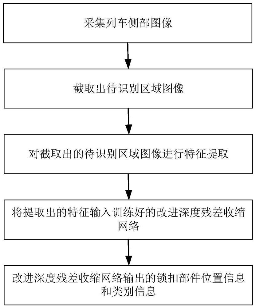
[0048] Specific implementation mode 1. Combination figure 1 and image 3 This embodiment will be described. A method for detecting a lock loss fault in this embodiment is specifically implemented through the following steps:

[0049] Collect the image of the side of the train, and cut out the image of the area of ​​the locking part to be identified from the collected image of the side of the train;

[0050] The VGG network is used to extract the feature of the image of the area to be identified that is cut out;

[0051] Through multi-level convolutional networks with different receptive fields, the deep abstract representation of the original image at different scales is extracted, that is, the image features at different depths;

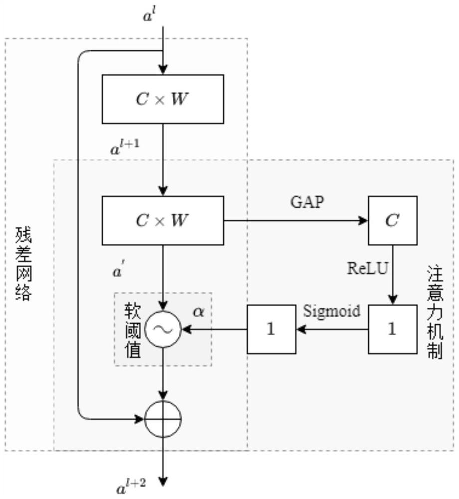
[0052] Input the extracted features into the trained improved deep residual shrinkage network, and output the position information and category information of the locking parts through the trained improved deep residual shrinkage network;

[005...

specific Embodiment approach 2

[0066] Embodiment 2: The difference between this embodiment and Embodiment 1 is that when the category information of the output locking component of the trained improved deep residual shrinkage network is an interference item or a fault that the current model does not have, it is considered that no detection has been made. failure, no alarm;

[0067] Otherwise, when the category information of the output lock parts is the fault existing in the current vehicle model, the output position information of the lock parts is mapped to the collected complete image of the side of the train to obtain the position of the fault in the complete image of the side of the train. Call the police.

specific Embodiment approach 3

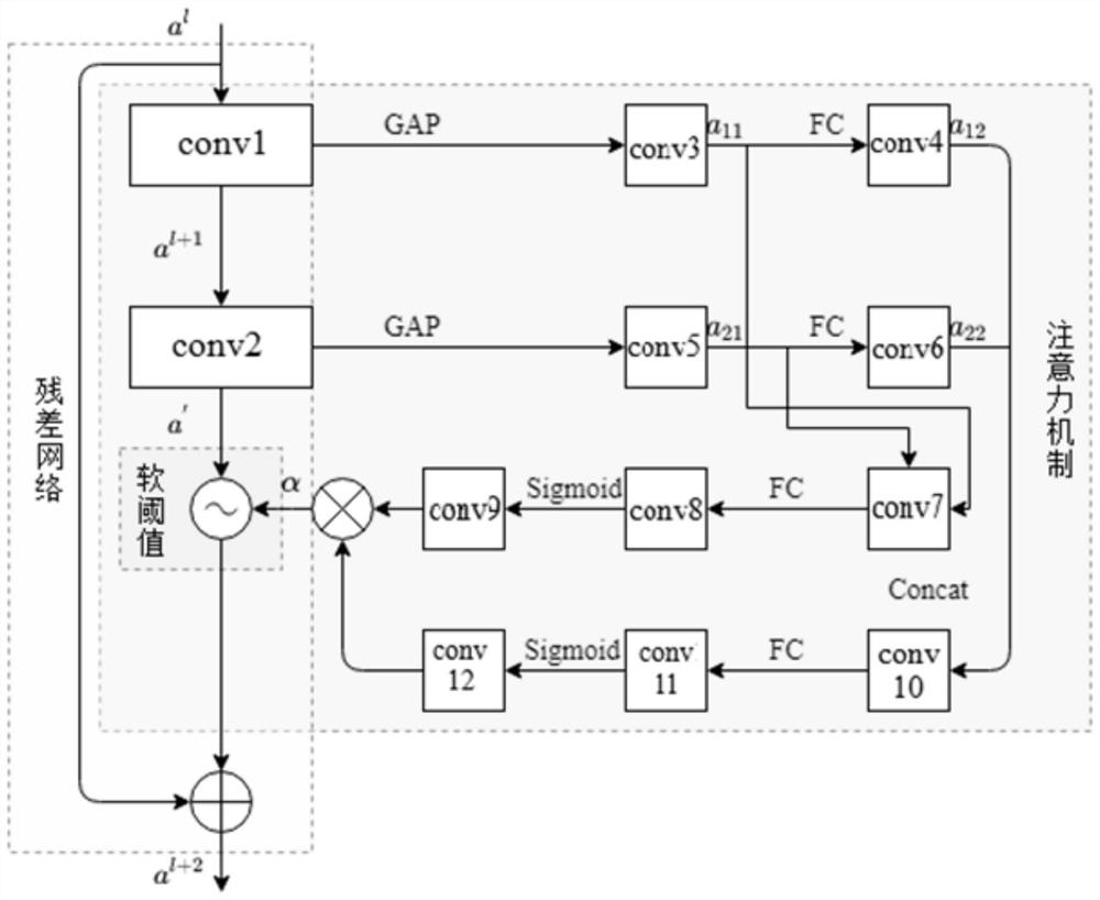
[0068] Embodiment 3: This embodiment differs from Embodiment 1 in that the first convolutional layer, the second convolutional layer, the third convolutional layer, the fourth convolutional layer, the fifth convolutional layer, and the sixth convolutional layer The number of channels of the product layer, the eighth convolution layer, and the ninth convolution layer are all C.

[0069] In the present invention, the value of the number of channels C is 3.


PUM


Abstract

The invention discloses a lock catch loss fault detection method, system and device, and belongs to the technical field of train lock catch loss fault detection. According to the invention, the problems of low detection accuracy and low detection efficiency when the lock catch loss fault is detected in a manual image checking mode are solved. The method is specifically realized through the following steps: collecting a complete image of the side part of a train, and intercepting a to-be-identified lock catch part image from the collected complete image of the side part of the train; carrying out feature extraction on the intercepted to-be-identified lock catch part image; inputting the extracted features into the trained improved deep residual shrinkage network, and outputting position information and category information of the lock catch component through the trained improved deep residual shrinkage network. The method can be applied to train lock catch loss fault detection.

Description

technical field [0001] The invention belongs to the technical field of train lock loss fault detection, and in particular relates to a lock loss fault detection method, system and device. Background technique [0002] The lock is the locking device of the train. Once the lock falls off, the train skirt may vibrate, loosen or even fall off, endangering personal safety and causing heavy losses. In order to ensure the smooth and safe operation of the train, it is necessary to identify and detect the locking situation. Once the phenomenon of falling off is found, it needs to be dealt with immediately. At present, manual inspection of images is used to inspect the lock for faults, and the inspection personnel are prone to fatigue and omissions during the work process, resulting in missed inspections and wrong inspections, resulting in low fault detection accuracy. Affecting driving safety, and the number of locks is large, the efficiency of manual inspection is low, and fault in...

Claims


Application Information

Patent Timeline
Patent Type & Authority Applications(China)
IPC IPC(8): G06K9/32G06K9/62G06N3/04
CPCG06V10/25G06N3/045G06F18/214
Inventor 王璐
Owner HARBIN KEJIA GENERAL MECHANICAL & ELECTRICAL CO LTD
Why Eureka
Try Eureka