Cooling transformer

A technology of transformers and refrigerators, applied in the field of transformers, can solve problems such as accelerating the aging of internal structure lines, affecting service life, and unsatisfactory heat dissipation effects of transformers, etc., to achieve the effect of ensuring cooling and cooling effects, ensuring cooling effects, and sufficient three-dimensional distribution

Inactive Publication Date: 2021-03-16
顾彩萍
View PDF0 Cites 0 Cited by
  • Summary
  • Abstract
  • Description
  • Claims
  • Application Information

AI Technical Summary

Problems solved by technology

[0003] The transformer has certain requirements on the temperature of its operating environment. When the internal temperature is too high, it is easy to accelerate the aging of the internal structure circuit, thereby affecting the service life; the heat dissipation design of the traditional transformer is relatively simple, and most of them use a heat dissipation port to communicate with the outside world. Heat exchange to achieve the purpose of heat dissipation and cooling, but when the outside temperature is high, the heat dissipation effect of the transformer will not be ideal, so there are certain limitations

Method used


Image

  • Cooling transformer
  • Cooling transformer
  • Cooling transformer

Examples


Embodiment 1

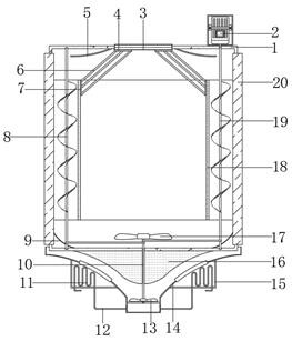
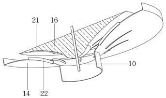
[0029] refer to Figure 1-4 , a cooling transformer, including a transformer main body 1, the bottom outer wall of the transformer main body 1 is fixedly installed with an air inlet arc end 14, and the end of the air inlet arc end 14 is equidistantly opened with an air outlet facing the edge of the transformer main body 1, The bottom outer wall of the transformer body 1 is fixed with a gas distribution block 16 by bolts, and the bottom outer wall of the gas distribution block 16 is provided with air guide grooves 21 distributed equidistantly, and the gas distribution block 16 is connected to the opposite side of the transformer body 1 through bearing rotation There is a rotating rod 10, and the two ends of the rotating rod 10 are respectively fixedly equipped with a blower vane 13 and a blower vane 2 17, and the outer wall of the bottom end of the air intake arc end 14 is fixed with a bottom water tank 15 by bolts, and the bottom water tank 15 Equidistantly distributed heat ex...

Embodiment 2

[0039] refer to Figure 5 , a cooling transformer. Compared with Embodiment 1, this embodiment also includes that the top end of the heat exchange connecting plate 6 is welded with heat exchange rings 24 whose specifications increase from top to bottom.

[0040] In the present invention, the top outer walls of the heat exchange ring fins 24 are fixedly installed with vertical fins 25 distributed equidistantly.

[0041] When the present invention is used: the heat exchange rings 24 arranged on the heat exchange connecting plate 6 are utilized, and because the specifications thereof increase sequentially from top to bottom, the three-dimensional distribution of the heat exchange rings 24 in space is relatively sufficient, and the vertical space of the vertical plates 25 is matched. The setting can further improve the heat exchange area and air conduction effect of the heat exchange ring plate 24, so as to achieve the purpose of ensuring the cooling effect of the transformer main...


PUM


Abstract

The invention belongs to the technical field of transformers, particularly relates to a cooling transformer, and aims to solve the problems that a traditional transformer is relatively simple in heatdissipation design, mostly adopts a mode of exchanging heat with the outside and is not ideal in heat dissipation effect under the condition of high outside weather temperature. The cooling transformer comprises a transformer main body, an air inlet arc end is fixedly installed on the outer wall of the bottom of the transformer main body, air outlets right facing the edge of the transformer main body are formed in the end of the air inlet arc end at equal intervals, and an air distribution block is fixed to the outer wall of the bottom of the transformer main body through bolts. By arranging aheat conduction block, a heat exchange inner sheet and a heat exchange connecting plate connected with the heat conduction block, heat conduction is conveniently utilized, an inner cover cylinder iseffectively cooled, and the inner cover cylinder can be in full contact with the heat exchange connecting plate in the air circulation process, so that the heat exchange area is increased, and the cooling effect of the transformer main body is further guaranteed; and through an air guide groove formed in a spiral top piece, the air guide effect of the spiral top piece can be improved.

Description

technical field [0001] The invention relates to the technical field of transformers, in particular to a cooling transformer. Background technique [0002] Electric power engineering refers to engineering related to the production, transmission, and distribution of electric energy. In a broad sense, it also includes engineering that uses electricity as power and energy in various fields. At the same time, it can be understood that the power transmission and transformation industry expansion project. The production of electric energy mainly relies on thermal power plants, hydropower plants and nuclear power plants. The principle of transformer transformation was first discovered by Faraday, but it was not until the 1880s that it began to be used in practice. In the competition that the power plant should output direct current and alternating current, the ability to use a transformer for alternating current is one of its advantages. Transformers can convert electrical energy...

Claims


Application Information

Patent Timeline
Patent Type & Authority Applications(China)
IPC IPC(8): H01F27/08H01F27/16H01F27/22
CPCH01F27/085H01F27/16H01F27/22
Inventor 顾彩萍
Owner 顾彩萍
Why Eureka
Try Eureka