
High-voltage cable deicing equipment for electric power detection

A power detection and high-voltage technology, applied in cable installation, electrical components, overhead installation, etc., can solve problems such as increase, cable damage, cable burden, etc.

Active Publication Date: 2021-03-16
诸暨恒达电机维修有限公司
View PDF8 Cites 5 Cited by
  • Summary
  • Abstract
  • Description
  • Claims
  • Application Information

AI Technical Summary

Problems solved by technology

[0002] Cable is a kind of electric energy or signal transmission device, which is usually composed of several wires or groups of wires. In cold winter, especially after snow or rain, the surface of the cable is more likely to freeze. After a long time, it is easy to More ice packs are formed on the surface of the cable, which brings a greater burden to the cable, which in turn causes the cable to be damaged and broken. Therefore, it is necessary to remove the ice in time, and the erection position of the cable is often in the field environment, which increases the corresponding increase. In addition to the difficulty of deicing, manual deicing is not only inefficient, but also has great dangers. However, the structure of today's deicing equipment is relatively complicated, which makes it more prone to rough ice breaking due to its heavy mass during deicing. The damage to the cable is not very practical, so a professional high-voltage cable deicing equipment is needed to solve this problem

Method used


Image

  • High-voltage cable deicing equipment for electric power detection
  • High-voltage cable deicing equipment for electric power detection
  • High-voltage cable deicing equipment for electric power detection

Examples


Embodiment

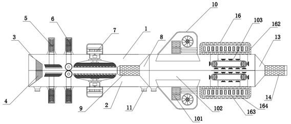
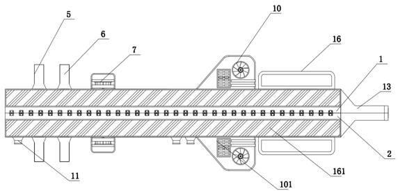
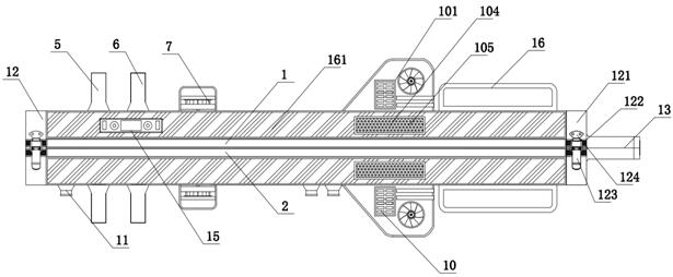
[0038] see Figure 1-8 , a high-voltage cable deicing device for power detection, comprising an upper casing 1 and a lower casing 2, the upper casing 1 and the lower casing 2 are hinged to each other through a hinge, the upper casing 1 and the lower casing The casings 2 are all made of plastic material, and the left end of the upper casing 1 and the lower casing 2 are fixedly connected with a half arc bucket 3, and the base body of the half arc bucket 3 is made of plastic material. The inner side of the half arc bucket 3 is fixedly connected with the heating arc plate 4, and the right side of the left end half arc bucket 3 in the upper casing 1 and the lower casing 2 is fixedly connected with the first deicing assembly 5. The inside of the upper housing 1 and the lower housing 2 on the right side of the first deicing assembly 5 are all fixedly installed with an ice-breaking assembly 6, and the inside of the upper housing 1 and the lower housing 2 on the right side of the ice-b...


PUM


Abstract

The invention discloses high-voltage cable deicing equipment for electric power detection, and the equipment comprises an upper housing and a lower housing, the middles of the upper housing and the lower housing are hinged to each other through a hinge part, the upper housing and the lower housing are housings made of a plastic material, and the left ends of the interiors of the upper housing andthe lower housing are fixedly connected with semi-arc buckets. A base body of each semi-arc bucket is made of plastic, heating arc plates are fixedly connected to the inner sides of the semi-arc buckets, first deicing assemblies are fixedly connected to the right sides of the semi-arc buckets at the left ends in the upper shell and the lower shell, ice breaking assemblies are fixedly installed atthe positions, on the right sides of the first deicing assemblies, in the upper shell and the lower shell, and second deicing assemblies are fixedly mounted in the upper shell and the lower shell on the right side of the ice breaking assemblies. The equipment is simple in structure, light, convenient and easy to carry, capable of effectively removing an ice layer on the surface of a cable, capableof guaranteeing the service life of the cable, high in practicability, wide in application prospect and worthy of application and popularization.

Description

technical field [0001] The invention relates to the technical field of cable deicing, in particular to a high-voltage cable deicing device for power detection. Background technique [0002] Cable is a kind of electric energy or signal transmission device, which is usually composed of several wires or groups of wires. In cold winter, especially after snow or rain, the surface of the cable is more likely to freeze. After a long time, it is easy to More ice packs are formed on the surface of the cable, which brings a greater burden to the cable, which in turn causes the cable to be damaged and broken. Therefore, it is necessary to remove the ice in time, and the erection position of the cable is often in the field environment, which increases the corresponding increase. In addition to the difficulty of deicing, manual deicing is not only inefficient, but also has great dangers. However, the structure of today's deicing equipment is relatively complicated, which makes it more pr...

Claims


Application Information

Patent Timeline
Patent Type & Authority Applications(China)
IPC IPC(8): H02G7/16
CPCH02G7/16
Inventor 杨毕女
Owner 诸暨恒达电机维修有限公司
Learn More