A kind of power distribution method and system for CT machine

A power supply and voltage technology, which is applied in the power distribution method and system field of CT machines, can solve problems such as surges, damage to other components and circuit boards, and reduction, and achieve the effect of avoiding shocks

Active Publication Date: 2022-07-26
FMI MEDICAL SYST CO LTD
View PDF12 Cites 0 Cited by
  • Summary
  • Abstract
  • Description
  • Claims
  • Application Information

AI Technical Summary

Problems solved by technology

The instantaneous power of CT power-on is as high as 100kVA. As long as the main switch of CT is closed, all circuit boards and components are also powered at the same time. At this time, the instantaneous voltage and current of the entire power supply system will be the largest. Almost all CT circuit boards and lines The interface will be subject to strong impact, which will damage the interface or circuit board or reduce its life, which is very unfavorable to the power supply system and CT system
The process of closing the air switch inside the CT will also generate a large surge, which will also cause damage to other components and circuit boards

Method used

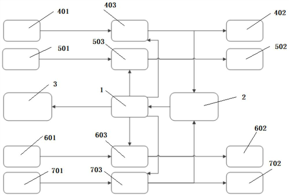
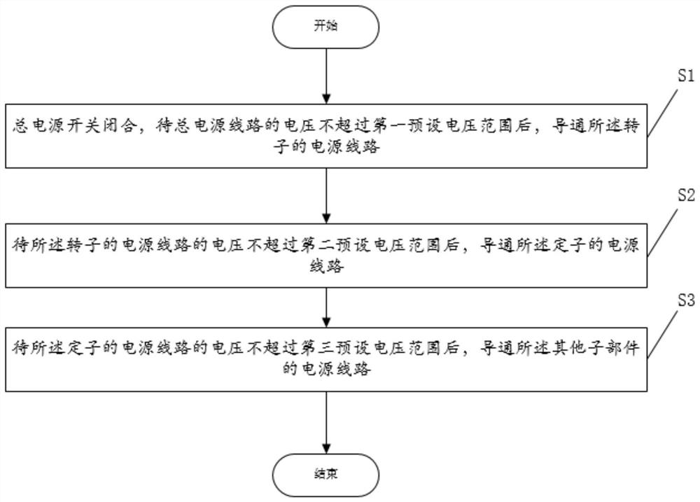
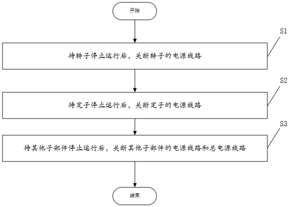

Image

  • A kind of power distribution method and system for CT machine
  • A kind of power distribution method and system for CT machine
  • A kind of power distribution method and system for CT machine

Examples


Embodiment Construction

[0022] The advantages of the present invention are further described below with reference to the accompanying drawings and specific embodiments.

[0023] Exemplary embodiments will be described in detail herein, examples of which are illustrated in the accompanying drawings. Where the following description refers to the drawings, the same numerals in different drawings refer to the same or similar elements unless otherwise indicated. The implementations described in the illustrative examples below are not intended to represent all implementations consistent with this disclosure. Rather, they are merely examples of apparatus and methods consistent with some aspects of the present disclosure, as recited in the appended claims.

[0024] The terminology used in the present disclosure is for the purpose of describing particular embodiments only and is not intended to limit the present disclosure. As used in this disclosure and the appended claims, the singular forms "a," "the," a...


PUM


Abstract

The invention provides a power distribution method and system for a CT machine, the main power supply line of the CT machine, the power supply line of the rotor, the power supply line of the stator, and the power supply lines of several other subcomponents There are power supply sampling circuits on the upper part to realize real-time monitoring of each power supply line. The main power switch is closed, and after the voltage of the main power line does not exceed the first preset voltage range, the power line of the rotor, the power line of the stator, and the power lines of the other sub-components are turned on in sequence to ensure that the When the voltage of the main power supply circuit is stable, the circuits of the rotor, the stator and other sub-components are turned on in sequence, so that the power-on sequence of each component can be controlled, and the huge voltage and current of the main power supply of the CT machine can be avoided. The surge impact on the circuits of the rotor, the stator and other sub-components also avoids the impact on the power system of the hospital where the CT machine is located.

Description

technical field [0001] The invention relates to the field of power supply control of computer tomography scanning equipment, in particular to a power distribution method and system for CT machines. Background technique [0002] As a large-scale medical electronic and electrical equipment, CT has a complex structure, high power, and many functional modules. There is mutual crosstalk between various components, and strong currents are closely related to weak parts. In order to make CT equipment work reliably, it is necessary to reduce the interference to other components among the electronic components, but also to improve their own anti-interference ability. [0003] The circuit boards of the CT stator part mainly include motion control boards, scanning control boards, audio communication boards, etc. The power supply of these circuit boards is provided by the electrical cabinet of the power supply with 220V AC power, and then through various switching power supplies to gener...

Claims


Application Information

Patent Timeline
Patent Type & Authority Patents(China)
IPC IPC(8): H02J3/00
CPCH02J3/00
Inventor 方泽莉朱炯黄振强
Owner FMI MEDICAL SYST CO LTD
Why Eureka
Try Eureka