Industrial two-layer fabric

A double-layer fabric, industrial technology, applied in the direction of fabrics, multi-strand fabrics, textiles, etc., can solve the problems of fiber, filler shedding, excessive surface space, penetration, etc., to meet rigidity, reduce water retention, and improve dehydration. sexual effect

Inactive Publication Date: 2021-03-16
FILCON
View PDF14 Cites 0 Cited by
  • Summary
  • Abstract
  • Description
  • Claims
  • Application Information

AI Technical Summary

Problems solved by technology

The fabric does not deform due to the cooperation of the 2 warp yarns to form a weave of 1 warp yarn on the surface, but one or both of the warp yarns must destroy their own weave, and they form a cross when going up and down part, and the warp yarns are arranged as one warp yarn in a group of two, and the two warp yarns are in a state of being arranged horizontally without overlapping on the line of one warp yarn, so the warp yarn binding yarn blocks the mesh near the weaving side weft yarn , there are cases where marks are caused on the paper due to partial changes in the dehydration characteristics of the thread
In addition, this industrial double-layer fabric has good dehydration performance due to the arrangement of dehydration holes completely penetrating from the upper side layer to the lower side layer on the entire surface. Or the fibers, fillers, etc. will fall off, and the generation of dehydration marks will become prominent
[0012] Furthermore, in existing industrial double-layer fabrics, a stack (onstack) structure is sometimes adopted in order to improve dehydration. In this structure, if the warp yarns are formed with different wire diameters up and down, the surface space becomes too large, and The space between the warp yarns on the side is widened and the space between the warp yarns on the bottom side is narrowed, so the control of the dehydration speed is insufficient.

Method used


Image

  • Industrial two-layer fabric
  • Industrial two-layer fabric
  • Industrial two-layer fabric

Examples


Embodiment approach 1

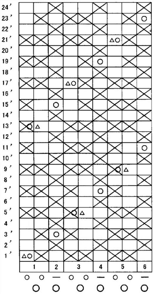
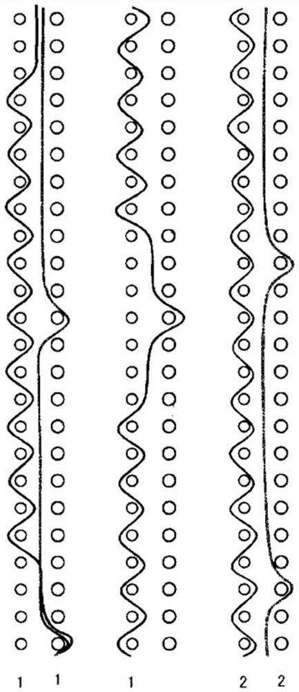
[0059] figure 2 It is a design drawing of Embodiment 1 of the industrial two-layer fabric of this invention. image 3 It is a partial side view arrangement diagram of Embodiment 1 of the industrial two-layer fabric of this invention. The first weave in Embodiment 1 is constituted by a set of two upper warp yarns and one lower warp yarn. The upper warp yarns in the first weave are formed of warp binding yarns having a function of binding the upper fabric and the lower fabric. In addition, a set of two upper warp yarns forming the first weave is arranged adjacent to each other to form a partial double flat weave on the surface of the upper weave. In addition, the second weave is constituted by one upper warp yarn and one lower warp yarn. The upper side warp yarns in the second weave are formed of flat warp yarns. Additionally, if figure 2As shown, the first tissue 1, 3, 5 and the second tissue 2, 4, 6 are arranged adjacently and alternately. Furthermore, the diameter of ...

Embodiment approach 2

[0065] Figure 4 It is a design drawing of Embodiment 1 of the industrial two-layer fabric of this invention. Figure 5 It is a partial side view arrangement diagram of Embodiment 2 of the two-layer fabric for industrial use of the present invention. The first weave in Embodiment 2 is constituted by a set of two upper warp yarns and one lower warp yarn. The upper warp yarns in the first weave are formed of warp binding yarns having a function of binding the upper fabric and the lower fabric. In addition, a set of two upper warp yarns forming the first weave is arranged adjacent to each other to form a partial double flat weave on the surface of the upper weave. In addition, the second weave is constituted by one upper warp yarn and one lower warp yarn. The upper side warp yarns in the second weave are formed of flat warp yarns. Additionally, if Figure 4 As shown, the first tissue 1, 3, 5 and the second tissue 2, 4, 6 are arranged adjacently and alternately. Furthermore,...

Embodiment approach 3

[0072] Image 6 It is a design drawing of Embodiment 3 of the industrial two-layer fabric of this invention. Figure 7 It is a partial side view arrangement diagram of Embodiment 3 of the two-layer fabric for industrial use of the present invention. The first weave in Embodiment 3 is constituted by a set of two upper warp yarns and one lower warp yarn. The upper warp yarns in the first weave are formed of warp binding yarns having a function of binding the upper fabric and the lower fabric. In addition, a set of two upper warp yarns forming the first weave is arranged adjacent to each other to form a partial double flat weave on the surface of the upper weave. In addition, the second weave is constituted by one upper warp yarn and one lower warp yarn. The upper side warp yarns in the second weave are formed of flat warp yarns. Additionally, if Image 6 As shown, the first tissue 1, 3, 5 and the second tissue 2, 4, 6 are arranged adjacently and alternately. Furthermore, t...


PUM


Abstract

Provided is an industrial two-layer fabric satisfying basic characteristics of a fabric, such as rigidity, wear resistance, dewaterability, mark suppression, and low water retention for reducing the amount of water retained. The industrial two-layer fabric pertaining to the present invention has at least a first structure and a second structure in the weave repeat thereof, the first structure being formed by a combination of two upper-surface-side warps and a single lower-surface-side warp, the second structure being formed by a single upper-surface-side warp and a single lower-surface-side warp, the first structure and the second structure being disposed adjacent to each other, the upper-surface-side warps in the first structure being formed by a warp binding yarn having the function of binding an upper-surface-side fabric and a lower-surface-side fabric, the combination of two upper-surface-side warps forming the first structure being disposed adjacent to each other and constitutinga partial rib weave at the surface of the upper-surface-side fabric, the diameter of the lower-surface-side warp being larger than the diameter of the upper-surface-side warp forming the first structure, and the upper-surface-side warp in the second structure being formed by a flat warp.

Description

technical field [0001] The present invention relates to a novel industrial double-layer fabric that has a thinner web thickness, is excellent in rigidity, abrasion resistance, dehydration, and trace suppression, and can support high-speed paper machines. In particular, it relates to a fabric with a flat yarn structure by combining a warp-heavy flat weave (acre weave) composed of two upper warp yarns and a flat warp yarn, thereby utilizing the slow dehydration and low Industrial double-layer fabric with water retention effect. Background technique [0002] Conventionally, fabrics woven from warp and weft yarns have been widely used as industrial fabrics, such as fabrics for papermaking, conveyor belts, filter cloths, etc., and fabric properties are required to suit each application and use environment. Among these fabrics, the requirements for papermaking fabrics used in papermaking processes such as dehydration of raw materials using the mesh of the fabric are particularly ...

Claims


Application Information

Patent Timeline
Patent Type & Authority Applications(China)
IPC IPC(8): D03D11/00D03D1/00D21F1/10
CPCD21F1/0036D03D15/46D03D11/00
Inventor 上田郁夫村上晋也梁井英之
Owner FILCON
Why Eureka
Try Eureka