
Dual or multi-shaft vacuum pump

A vacuum pump, emergency technology, applied in the direction of pumps, pump components, pump control, etc., can solve the problem that the lubricant cannot be completely far away from the pump, complicated, etc.

Inactive Publication Date: 2021-03-16
レイボルドゲーエムベーハー
View PDF24 Cites 1 Cited by
  • Summary
  • Abstract
  • Description
  • Claims
  • Application Information

AI Technical Summary

Problems solved by technology

Geared transmissions require a continuous lubricant supply, which is complex to implement in terms of construction in dry compression vacuum pumps
Even for shaft seals with a highly complex structure, the lubricant cannot be kept completely away from the suction chamber of the pump, which leads to undesired interactions with pumped substances

Method used


Image

  • Dual or multi-shaft vacuum pump
  • Dual or multi-shaft vacuum pump
  • Dual or multi-shaft vacuum pump

Examples


Embodiment Construction

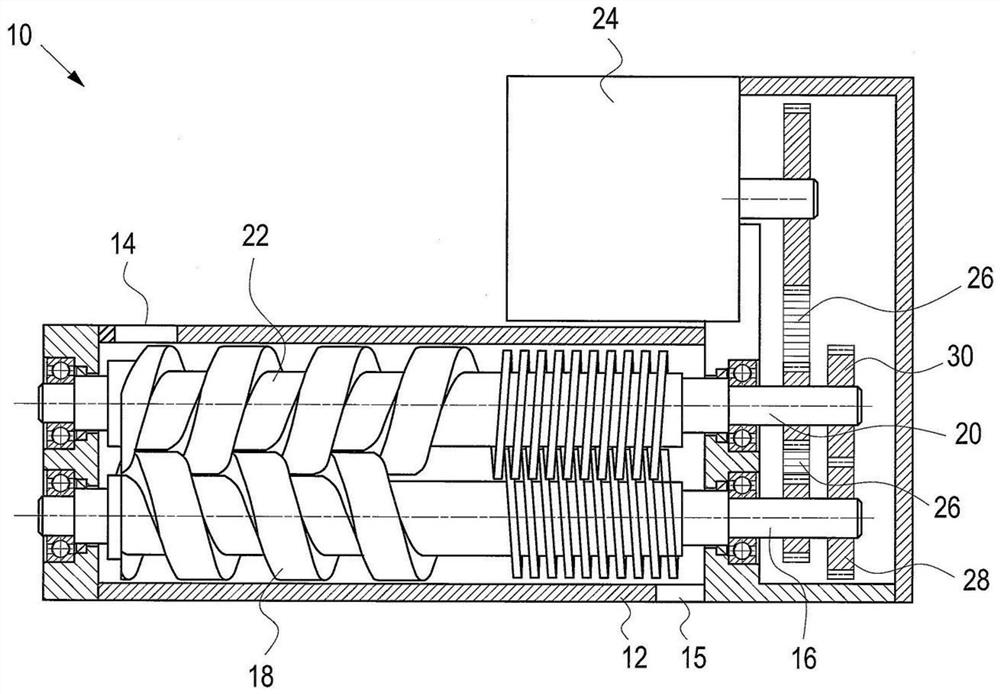
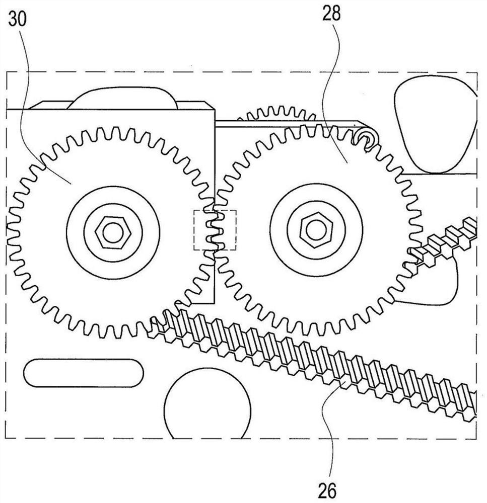
[0023] The vacuum pump 10 according to the invention is designed as a screw pump comprising a housing 12 with an inlet 14 and an outlet 15 . In the example shown, the first shaft 16 is arranged in the housing 12 and the first pump element 18 is designed as a screw body. Furthermore, a second shaft 20 is arranged in the housing 12 , the second shaft 20 having a second pump body 22 likewise designed as a screw body. The first pump member 18 and the second pump member 22 mesh with each other. Furthermore, a motor 24 is provided, which can be designed as an electric motor. The first shaft 16 and the second shaft 20 are respectively rotated or driven by a motor 24 by means of a drive belt 26 . The rotation of the shafts 16, 20 is performed in opposite directions, so that the gaseous medium is conveyed from the inlet 14 to the outlet. In order to generate an effective vacuum, the distance between the pump elements 18, 22 is required to be very small. At the same time, the pump e...


PUM


Abstract

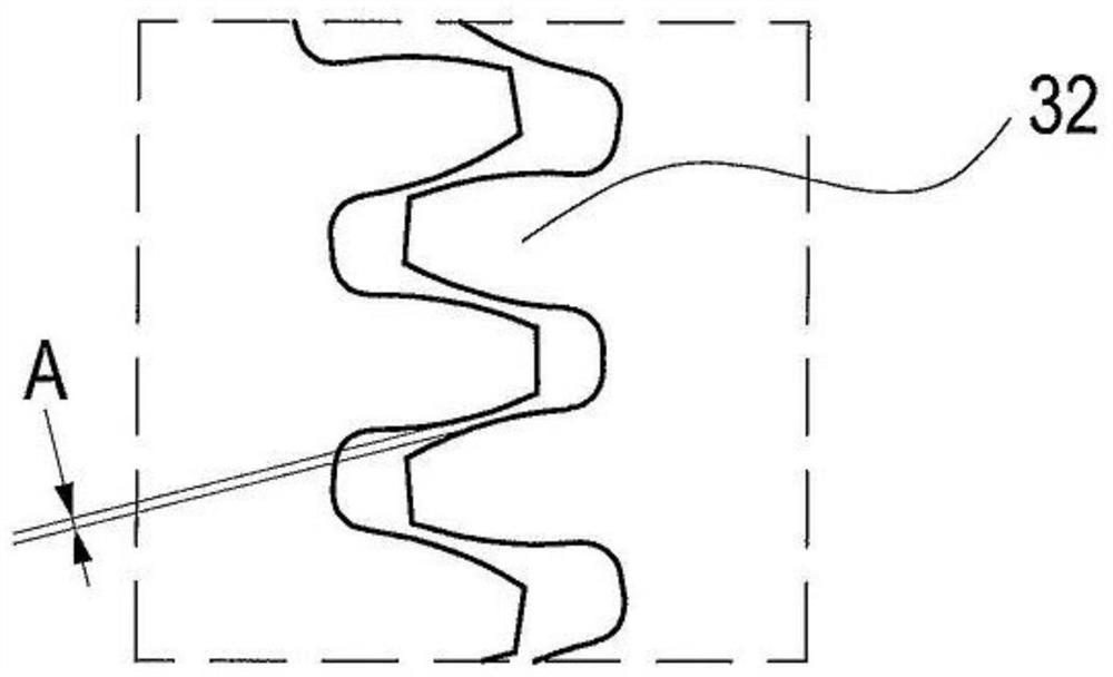
The invention relates to a dual or multi-shaft vacuum pump comprising a motor, a first shaft and at least a second shaft, wherein the first shaft and the second shaft are driven synchronously by the motor via a common drive belt. The first shaft has a pumping element, and the second shaft likewise has a pumping element, which cooperates with the pumping element of the first shaft in order to convey a gaseous medium from an inlet to an outlet. The first shaft has a first emergency running gear, and the second shaft likewise has a second emergency running gear, which meshes with the first emergency running gear.

Description

【Technical field】 [0001] The invention relates to a twin-shaft or multi-shaft vacuum pump for generating vacuum. 【Background technique】 [0002] A known twin-shaft vacuum pump comprises a housing and a motor. A first shaft carrying a first pumping element and a second shaft carrying a second pumping element are arranged in the housing. The shaft is rotated by means of a motor. The two pump elements cooperate with each other such that the gaseous medium is conveyed from the inlet to the outlet of the housing. [0003] In order to efficiently generate a vacuum with a twin-shaft vacuum pump, the pump elements may only have a small distance and thus also only a small circumferential backlash. However, contact between pump elements must be avoided. For this, the shafts need to be driven synchronously. In the event of loss of said synchronization, the pump parts come into contact with each other, which can lead to serious damage or even destruction of the vacuum pump. [000...

Claims


Application Information

Patent Timeline
Patent Type & Authority Applications(China)
IPC IPC(8): F01C17/00F04C18/12F04C18/16F04C28/28F04C29/00F04C25/02
CPCF04C18/12F04C18/16F04C29/005F01C17/00F04C28/28F04C25/02F04C2240/81F04C23/02F04C29/0085F04C2240/40F04C2240/60F05B2240/60F05B2210/12F04C2220/10F04C2270/12F04C2270/16
Inventor 德克·席勒沃尔夫冈·吉伯曼克劳斯彼得·斯克里克托马斯·德赖费特
Owner レイボルドゲーエムベーハー
Learn More