
Electric mini-tiller for agricultural use

The technology of an electric micro-tiller and micro-tiller for agricultural use is applied in the fields of tillage implements, agricultural machinery and implements, applications, etc. It can solve problems such as insufficient technology, insufficient ditching, and soil clods slipping in the ditch, etc. The ditch effect is good, the effect of avoiding truncation in the ditch, and avoiding the effect of secondary ditching

Inactive Publication Date: 2021-03-19
张晓丹
View PDF2 Cites 0 Cited by
  • Summary
  • Abstract
  • Description
  • Claims
  • Application Information

AI Technical Summary

Problems solved by technology

[0002] Agriculture is the basic industry that provides support for the construction and development of the national economy. It is an industry that uses the growth and development laws of animals and plants to obtain products through artificial cultivation. When small-scale farmland is cultivated, it is necessary to loosen the soil and ditch the land. Most of them use The electric micro tillage machine is used for farming, but the existing electric micro tillage machine is not perfect enough. During ditching, the soil is discharged to both sides of the ditch. Because there are soil clods in the soil, and the soil clods have a certain gravity, so It will cause the soil clods to slide down in the ditch, and the soil clods will slide down with some scattered soil, so the ditching is not thorough enough. At the same time, the ditch will be cut off due to the existence of the soil clods, and a second ditching is required

Method used


Image

  • Electric mini-tiller for agricultural use
  • Electric mini-tiller for agricultural use
  • Electric mini-tiller for agricultural use

Examples


Embodiment

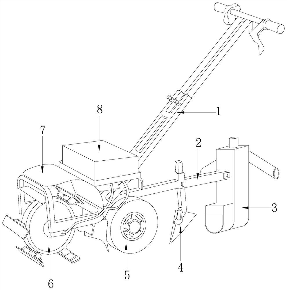
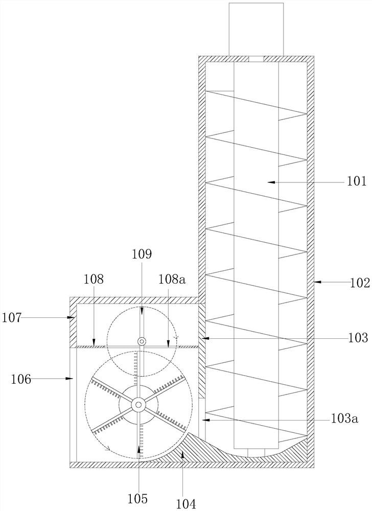
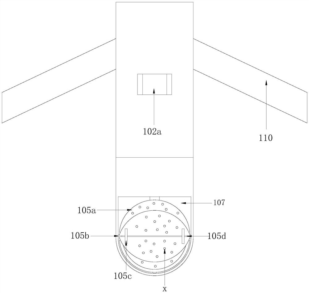
[0026] see Figure 1-7 , the present invention provides a technical solution for an agricultural electric tiller: its structure includes an armrest frame 1, a body 2, a soil collection device 3, a plow share 4, a walking wheel 5, a tiller knife group 6, and a dust cover 7. Power pack 8, the body 2 is equipped with a walking wheel 5, one side of the walking wheel 5 is provided with a tiller knife group 6 connected to the body 2, and the other side is provided with a soil collection device 3, a plow Head 4, the plow share 4 is located between the falling soil collection device 3 and the road wheels 5, a power pack 8 is installed on the top of the body 2, the power pack 8 is electrically connected to the road wheels 5, and the tiller A dustproof cover 7 is arranged above the knife set 6, and the dustproof cover 7 is mechanically connected with the body 2, and the side of the power pack 8 away from the dustproof cover 7 is provided with an armrest frame 1 connected with the body 2...


PUM


Abstract

The invention discloses an electric mini-tiller for agricultural use. The electric mini-tiller for agricultural use structurally comprises an arm-rest frame, a machine body, a falling soil collectingdevice, a plough head, road wheels, a mini-tiller knife tackle, a dustproof cover and a power pack, wherein the road wheels are mounted on the machine body; sides of the road wheels are equipped withthe mini-tiller knife tackle connected with the machine body; and the falling soil collecting device and the plough head are arranged on the other sides of the road wheels. Compared with the prior art, the electric mini-tiller has the beneficial effects that: the falling soil collecting device is additionally arranged on the current electric mini-tiller, so that falling soil can be immediately collected after ditching, the collected falling soil can be discharged on the two outer sides of a ditch and can be prevented from sliding into the ditch again, and thus, in-ditch cut-off is avoided, secondary ditching can be avoided, and the ditching effect is good.

Description

technical field [0001] The invention relates to the technical field of agricultural machinery, in particular to an agricultural electric tiller. Background technique [0002] Agriculture is the basic industry that provides support for the construction and development of the national economy. It is an industry that uses the growth and development laws of animals and plants to obtain products through artificial cultivation. When small-scale farmland is cultivated, it is necessary to loosen the soil and ditch the land. Most of them use The electric micro tillage machine is used for farming, but the existing electric micro tillage machine is not perfect enough. During ditching, the soil is discharged to both sides of the ditch. Because there are soil clods in the soil, and the soil clods have a certain gravity, so It will cause the soil clods to slide down in the ditch, and the soil clods will slide down with some scattered soil, so the ditching is not thorough enough. At the sa...

Claims


Application Information

Patent Timeline
IPC IPC(8): A01B49/02A01B33/02A01B33/10A01B33/08A01B13/16A01B17/00
CPCA01B13/16A01B17/00A01B33/021A01B33/08A01B33/103A01B49/022
Inventor 张晓丹
Owner 张晓丹
Learn More