
Discharging and feeding structure used for spring machining equipment and using method

A processing equipment and discharge technology, applied in the field of spring processing, can solve the problems of error-prone spring pushing, low processing efficiency, unreasonable and other problems, and achieve the effect of strong reliability

Inactive Publication Date: 2021-03-19
廖雪松
View PDF3 Cites 0 Cited by
  • Summary
  • Abstract
  • Description
  • Claims
  • Application Information

AI Technical Summary

Problems solved by technology

[0007] Aiming at the above-mentioned deficiencies in the prior art, the present invention provides a material-discharging and feeding structure for spring processing equipment, which is used to solve the problem of spring pushing during the material-discharging and feeding process of existing spring processing equipment. Error-prone, resulting in the spring not being able to accurately enter the next processing station to be chamfered. At the same time, when the spring is blocked, it cannot be cleaned reasonably and effectively, resulting in low processing efficiency, especially when processing different batches of springs. Due to the different spring lengths , does not match the width of the pusher part, and the pusher part will push the two springs to be processed without intervals to the next station at the same time, causing the springs to fail to feed and the processing procedure to be disordered

Method used


Image

  • Discharging and feeding structure used for spring machining equipment and using method
  • Discharging and feeding structure used for spring machining equipment and using method
  • Discharging and feeding structure used for spring machining equipment and using method

Examples


Embodiment 1

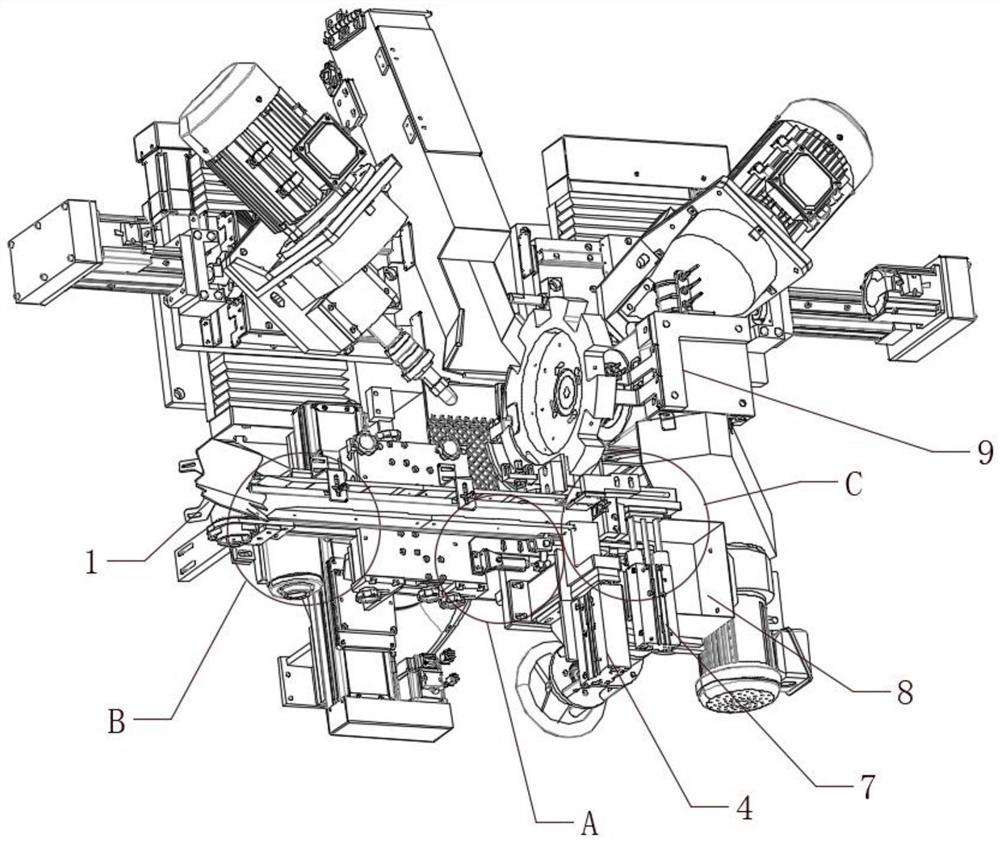
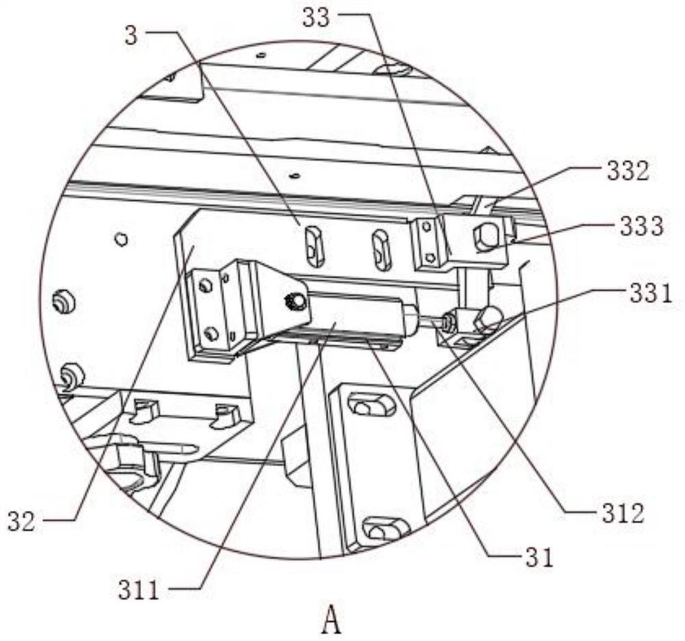
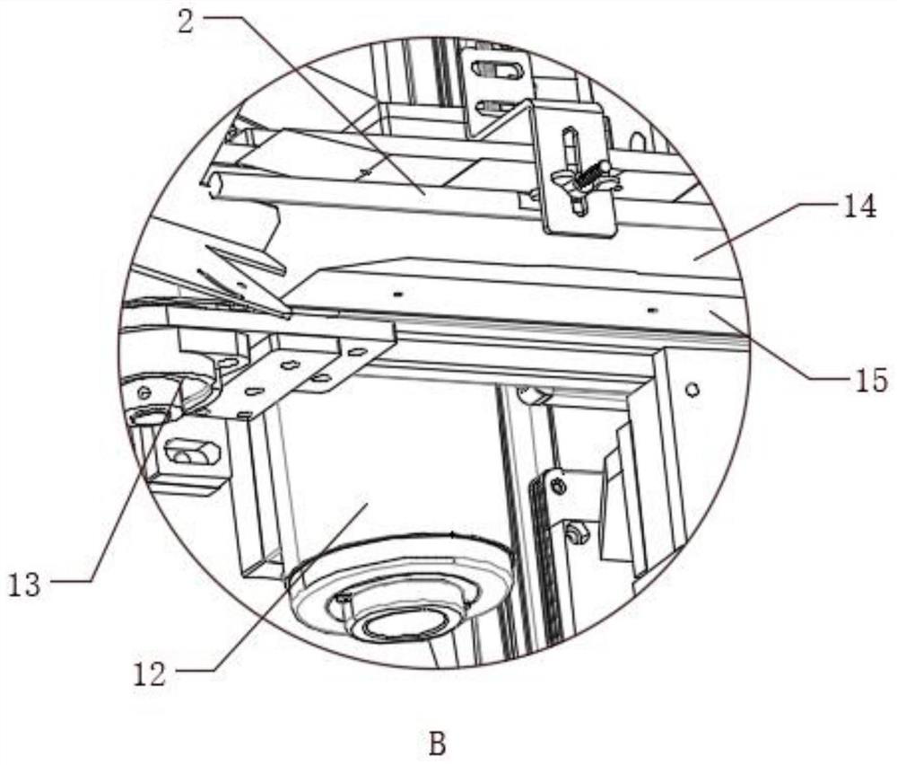
[0056] Such as Figure 1-7As shown, a discharge and feeding structure for spring processing equipment of the present invention includes a discharge conveying body 1, a guide assembly 2, a material pushing mechanism 3, and a push cylinder assembly 4, and the guide assembly 2 is arranged on the conveying body 1 At the upper end, the pushing mechanism 3 is connected to the outside of the discharge conveying body 1, and the push cylinder assembly 4 is connected to the upper end of the discharge conveying body 1, and the push cylinder assembly 4 is located on the right side of the push mechanism 3, and the discharge conveying body The right end of 1 is provided with a spring push port 11, the head of the push cylinder assembly 4 is facing the spring push port 11, and the push mechanism 3 includes a push cylinder body 31, a push cylinder support 32 and a push linkage unit 33 , the dial cylinder support 32 is connected with the outside of the discharge conveying body 1, the tail of t...

Embodiment 2

[0070] This embodiment is a further improvement of the previous embodiment, such as Figure 1-7 As shown, a discharge and feeding structure for spring processing equipment of the present invention includes a discharge conveying body 1, a guide assembly 2, a material pushing mechanism 3, and a push cylinder assembly 4, and the guide assembly 2 is arranged on the conveying body 1 At the upper end, the pushing mechanism 3 is connected to the outside of the discharge conveying body 1, and the push cylinder assembly 4 is connected to the upper end of the discharge conveying body 1, and the push cylinder assembly 4 is located on the right side of the push mechanism 3, and the discharge conveying body The right end of 1 is provided with a spring push port 11, the head of the push cylinder assembly 4 is facing the spring push port 11, and the push mechanism 3 includes a push cylinder body 31, a push cylinder support 32 and a push linkage unit 33 , the dial cylinder support 32 is conne...

Embodiment 3

[0087] This embodiment is a further improvement of the previous embodiment, such as Figure 1-7 As shown, a discharge and feeding structure for spring processing equipment of the present invention includes a discharge conveying body 1, a guide assembly 2, a material pushing mechanism 3, and a push cylinder assembly 4, and the guide assembly 2 is arranged on the conveying body 1 At the upper end, the pushing mechanism 3 is connected to the outside of the discharge conveying body 1, and the push cylinder assembly 4 is connected to the upper end of the discharge conveying body 1, and the push cylinder assembly 4 is located on the right side of the push mechanism 3, and the discharge conveying body The right end of 1 is provided with a spring push port 11, the head of the push cylinder assembly 4 is facing the spring push port 11, and the push mechanism 3 includes a push cylinder body 31, a push cylinder support 32 and a push linkage unit 33 , the dial cylinder support 32 is conne...


PUM


Abstract

The invention belongs to the technical field of spring machining, and particularly relates to a discharging and feeding structure used for spring machining equipment. The discharging and feeding structure comprises a discharging conveying body, a guide assembly, a material shifting mechanism and a pushing cylinder assembly. The guide assembly is arranged at the upper end of the conveying body, thematerial shifting mechanism is connected with the outer side of the discharging conveying body, the pushing air cylinder assembly is connected with the upper end of the discharging conveying body, the pushing air cylinder assembly is located on the right side of the material shifting mechanism, and a spring pushing opening is formed in the right end of the discharging conveying body. According tothe discharging and feeding structure, the problems that in existing spring machining equipment, errors are prone to happening to spring pushing in the discharging and feeding process, meanwhile, when springs are blocked, the springs cannot be reasonably and effectively removed, especially when springs of different batches are treated, due to the fact that the lengths of the springs are differentand are not matched with the width of a pushing component, the pushing component can push the two to-be-machined springs without intervals to the next step at the same time, the springs cannot be fed, and the machining procedure is disordered are solved.

Description

technical field [0001] The invention belongs to the technical field of spring processing, in particular to a material discharging and loading structure for spring processing equipment and a use method. Background technique [0002] A spring is a mechanical part that uses elasticity to work. Parts made of elastic materials are deformed under the action of external force, and return to their original shape after the external force is removed. Spring is one of the basic mechanical parts, and it is widely used in various fields of national economy and social life. Therefore, to optimize the spring processing equipment-spring forming machine, improve its equipment structure, and make it more reasonable is the common wish of equipment manufacturers and spring manufacturers, especially in the field of chamfering the two ends of the spring. The spring chamfering machine is used. The chamfering machine is a small precision machine tool specially used for chamfering of mold manufactu...

Claims


Application Information

Patent Timeline
Patent Type & Authority Applications(China)
IPC IPC(8): B21F11/00B21F23/00
CPCB21F11/005B21F23/005
Inventor 廖雪松
Owner 廖雪松
Learn More