Metal surface ultrasonic machining device and machining method

A processing device and metal surface technology, applied in the field of metal surface ultrasonic processing devices, can solve the problems of ultrasonic tool offset, irregular metal surface processing, etc.

Inactive Publication Date: 2021-03-19
张家港东艺超声有限公司
View PDF4 Cites 0 Cited by
  • Summary
  • Abstract
  • Description
  • Claims
  • Application Information

AI Technical Summary

Problems solved by technology

[0005] One of the purposes of the present invention is to solve the problem that the ultrasonic tool is offset on the surface of the workpiece in the prior art, resulting in irregular processing of the metal surface

Method used


Image

  • Metal surface ultrasonic machining device and machining method
  • Metal surface ultrasonic machining device and machining method
  • Metal surface ultrasonic machining device and machining method

Examples


Embodiment 1

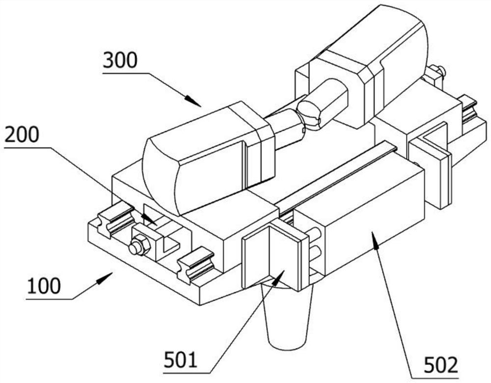
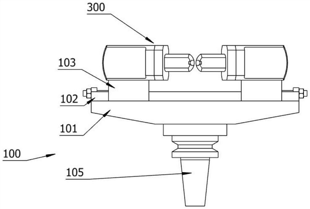
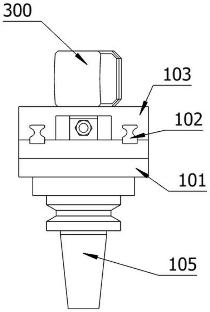
[0047] Such as figure 1 , 2 , 3, 4, 5, 6, 7, and 8, this embodiment discloses an ultrasonic metal surface processing device, which is characterized in that it includes: a main body 100, a base 101, a track 102, a slider 103, a tool holder The assembly 200, the ultrasonic cutter 300, and the main body 100 include: the base 101 is a metal element, and the surface of the base 101 is arranged flush; there are two rails 102, and the rails 102 are arranged on the base 101, leaving a distance between the rails 102; There are two sliders 103, and the sliders 103 are respectively arranged at the two ends of the track 102, there is a chute 104 below the slider 103, the chute 104 of the slider 103 is connected with the track 102, and the slider 103 is movably connected with the track 102, The slide block 103 translates left and right along the extending direction of the track 102; the knife rest assembly 200 is provided with two and is symmetrically arranged, and the two knife rest asse...

Embodiment 2

[0057] Same as Embodiment 1, also includes such as Figure 7 , 8 , 9, 10, and 11 show that the balance assembly 400 is arranged under the two sliders 103 and is connected with the two slider connectors 202. The balance assembly 400 includes a balance connecting rod 401203, a spherical joint 202, and a spherical joint 202 connector, leading out Joint 405; one end of the spherical joint 202 is connected to the slider connecting piece 202, and the connecting piece of the spherical joint 202 is movably connected to the spherical joint 202. There are two connecting pieces of the spherical joint 202, which are respectively an outer ring 403 and an inner ring 404, respectively It can rotate in different directions, which can better adapt the ultrasonic cutter 300 to different curved surfaces. One end of the lead-out joint 405 is movably connected to the spherical joint 202 connector, and the other end is connected to the ultrasonic cutter 300. When the ultrasonic cutter 300 deflects ...

Embodiment 3

[0060] Such as Figure 12 As shown, a processing method of a metal surface ultrasonic processing device is finally provided, comprising the following steps:

[0061] The base 101 is fixed, the object to be processed is placed between the two ultrasonic cutters 300, the two-way cylinder 502 moves, and the slider 103 is adjusted by the two-way cylinder 502 to change the distance between the two ultrasonic cutters 300, so that the ultrasonic cutter 300 is in contact with the surface of the processed object, and the ultrasonic tool 300 exerts a certain pressure during the processing;

[0062] The processed object is processed by the ultrasonic tool 300 as it moves. While the ultrasonic tool 300 is moving on the surface of the workpiece, the two sides of the ultrasonic tool 300 touch the surface of the object to be processed at the same time, and the external extrusion forces on the workpiece during the processing cancel each other out. ;

[0063] The balance component 400 mainta...


PUM


Abstract

The invention relates to the technical field of ultrasonic machining, in particular to a metal surface ultrasonic machining device. The device comprises a main body, wherein the main body comprises abase which is a metal element, the surface of the base is a flat surface; two rails are arranged, and the rails are arranged on the base; two sliding blocks are arranged, the sliding blocks are separately arranged at the two ends of the rails, sliding grooves are formed below the sliding blocks, and the sliding grooves of the sliding blocks are connected to the rails in a matched mode; two knife rest assemblies are arranged, and the knife rest assemblies are symmetrically arranged, each knife rest assembly comprises a base connecting piece arranged at one end of the base; and the sliding blockconnecting pieces are arranged below the sliding blocks, connecting rods are arranged inside the base connecting pieces, the connecting rods are movably connected to the sliding block connecting pieces, and the sliding blocks moves in an extending direction of the connecting rods through the sliding block connecting pieces. An ultrasonic cutter is arranged on the upper surfaces of the sliding blocks, and the problem that in the prior art, an ultrasonic cutter deviates on the surface of a workpiece, and consequently metal surface machining is irregular is solved.

Description

technical field [0001] The invention relates to the technical field of ultrasonic processing, in particular to an ultrasonic processing device and a processing method for metal surfaces. Background technique [0002] Many curved surface parts are processed by CNC machine tools. The spindle of the CNC machine tool and multiple coordinates of the worktable perform linear interpolation motion at the same time, so that the tool moves according to the required spatial trajectory to complete the processing of the corresponding complex surface. During the machining process, the phenomenon of knife dropping or jumping will occur, which will affect the machining accuracy of the blade surface. [0003] Ultrasonic processing of metal surfaces can obtain low roughness values ​​and high processing accuracy, and has the characteristics of high efficiency and low cost. Ultrasonic machining of metal surfaces is accomplished by ultrasonic tools. Different ultrasonic tools can process surfac...

Claims


Application Information

Patent Timeline
Patent Type & Authority Applications(China)
IPC IPC(8): B23P9/00B23P9/04
CPCB23P9/00B23P9/04
Inventor 李宜兵
Owner 张家港东艺超声有限公司
Why Eureka
Try Eureka