Pit removing machine

The technology of a pit lifter and a hydraulic motor is applied in vehicle maintenance, shunting equipment, vehicle control devices, etc., which can solve the problems of tires falling into pits and unable to escape, and achieve the effect of simple operation.

Inactive Publication Date: 2021-03-19
侯聪
View PDF0 Cites 0 Cited by
  • Summary
  • Abstract
  • Description
  • Claims
  • Application Information

AI Technical Summary

Problems solved by technology

[0003] In view of the above problems, the present invention provides a pit-extracting machine, which solves the problem that the tires of the automobile fall into the pit and cannot escape

Method used


Image

  • Pit removing machine
  • Pit removing machine
  • Pit removing machine

Examples


Embodiment

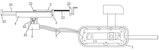
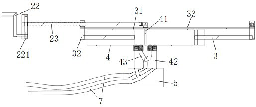
[0026] like figure 1 - As shown in 5, a pit remover includes a base 1, a push rod 2, a piston rod 3, a hydraulic pipe 4, a confluence valve 5, a hydraulic motor 6 and two oil pipes 7,

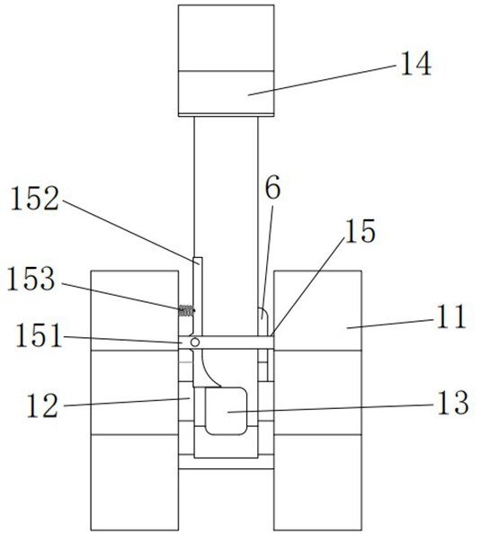
[0027] The base 1 includes two crawler belts 11, several connecting rods 12 connecting the two crawler belts 11 together, a crowbar 13, a top seat 14 and a limit assembly 15, and the crowbar 13 and one of the connecting rods 12 connection; the top seat 14 is connected to the connection between the pry bar 13 and the connecting rod 12; the limit assembly 15 includes a support plate 151, a top plate 152 and a spring, and the two ends of the support plate 151 are respectively connected to two crawlers 11, the top plate 152 is connected to the support plate 151, the top plate 152 is an L-shaped structure, and the middle part of the top plate 152 is overlapped with one side of the crowbar 13; the two ends of the spring are respectively connected to the track 11 and the top of the top plate 152; the...


PUM


Abstract

A pit removing machine comprises a base, a push rod, a piston rod, a hydraulic pipe, a confluence valve, a hydraulic motor and two oil pipes, the base comprises two crawler belts, a plurality of connecting rods for connecting the two crawler belts together, a pinch bar, a top seat and a limiting assembly, and the pinch bar is connected with one connecting rod; the top seat is connected to the joint of the pry bar and the connecting rod; the push rod is connected to the middle of the top of the hydraulic pipe, a crank handle is arranged at the other end of the push rod, and a threaded rod is arranged between the middle of the push rod and the rocking handle. A piston head of the piston rod is positioned in the hydraulic pipe; a rectangular block with an opening thread matched with the thread of the push rod is arranged at the other end of the piston rod; the two piston rods are located at the two ends of the hydraulic pipe respectively. A clapboard is arranged in the middle of the hydraulic pipe; two pairs of oil inlet pipes and oil outlet pipes are arranged at the bottom of the hydraulic pipe and located on the two sides of the partition plate correspondingly and connected with thehydraulic motor through oil pipes. The problem that a tire of an automobile sinks into a pit and cannot get rid of the pit is solved.

Description

technical field [0001] The invention relates to the technical field of automobile auxiliary equipment, in particular to a pit remover. Background technique [0002] The invention of the automobile has brought great convenience to people's travel; with the continuous development of the automobile industry, people not only require the safety and comfort of driving a car, but also require the versatility of the car; but when the car is driving in the desert When driving on a middle or muddy dirt road, due to the influence of factors such as weather conditions or geographical environment, the tires of the car often fall into sand pits or dirt pits, and at this moment they cannot drive away and are trapped. Contents of the invention [0003] In view of the above problems, the present invention provides a pit escape machine, which solves the problem that the tires of automobiles fall into the pit and cannot escape. [0004] The technical solution used in the present invention i...

Claims


Application Information

Patent Timeline
Patent Type & Authority Applications(China)
IPC IPC(8): B60S13/02
CPCB60S13/02
Inventor 侯聪
Owner 侯聪
Why Eureka
Try Eureka