Buried pipe network measurement and control device
A measurement and control device, buried technology, applied in water supply devices, water supply devices, water supply main pipelines, etc., can solve the problems of few monitoring parameters, insufficient water supply, time-consuming, etc., to achieve small excess pressure, reduce energy consumption, and reduce explosion. The effect of managing risk
- Summary
- Abstract
- Description
- Claims
- Application Information
AI Technical Summary
Problems solved by technology
Method used
Image

Examples
Embodiment Construction
[0014] Below in conjunction with specific embodiment, further illustrate the present invention. It should be understood that these examples are only used to illustrate the present invention and are not intended to limit the scope of the present invention. In addition, it should be understood that after reading the teachings of the present invention, those skilled in the art can make various changes or modifications to the present invention, and these equivalent forms also fall within the scope defined by the appended claims of the present application.
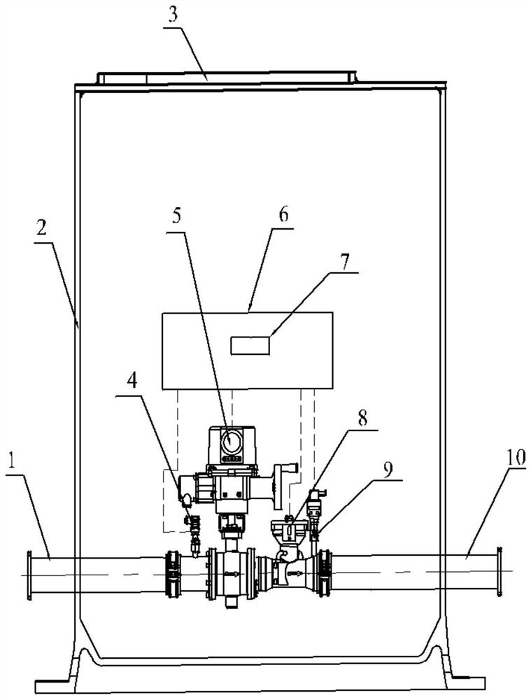
[0015] The embodiment of the present invention relates to a buried pipe network measurement and control device, such as figure 1 As shown, it includes an inlet pipe 1, a cylinder body 2, a manhole 3, an inlet pressure sensor 4, a flow regulator 5, a data collector 6, a controller 7, a flow sensor 8, an outlet pressure sensor 9 and an outlet pipe 10.
[0016] Further, the inlet pipe 1 is arranged on one side of the cylinder bod...
PUM
 Abstract
Description
Claims
Application Information