Axial expansion self-compensating device for aero-engine turbine part tester

An aero-engine and component testing technology, which is applied in the expansion compensation device for pipelines, engine testing, jet engine testing, etc., can solve the problems of cumbersome installation and disassembly, limited application scenarios, and low flexibility, so as to improve the service life , widen the application environment and avoid fatigue damage

Active Publication Date: 2021-03-19
AECC SICHUAN GAS TURBINE RES INST
View PDF12 Cites 0 Cited by
  • Summary
  • Abstract
  • Description
  • Claims
  • Application Information

AI Technical Summary

Problems solved by technology

[0004] Provides an axial expansion self-compensating device for aero-engine turbine component testers, which solves the defects of limited application scenarios, low flexibility, and cumbersome installation and disassembly caused by the common structure of high-temperature and high-pressure steering components, and at the same time improves the service life and reduces Design, processing, and maintenance costs, providing steering components capable of expansion self-compensation for high-temperature, high-pressure fluids in various industries

Method used


Image

  • Axial expansion self-compensating device for aero-engine turbine part tester
  • Axial expansion self-compensating device for aero-engine turbine part tester
  • Axial expansion self-compensating device for aero-engine turbine part tester

Examples


Embodiment Construction

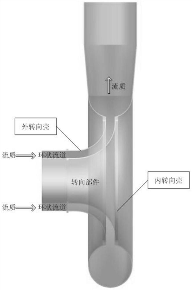
[0025] The turning parts of the annular flow channel generally include two turning sections inside and outside, and the common forms are as figure 1 .

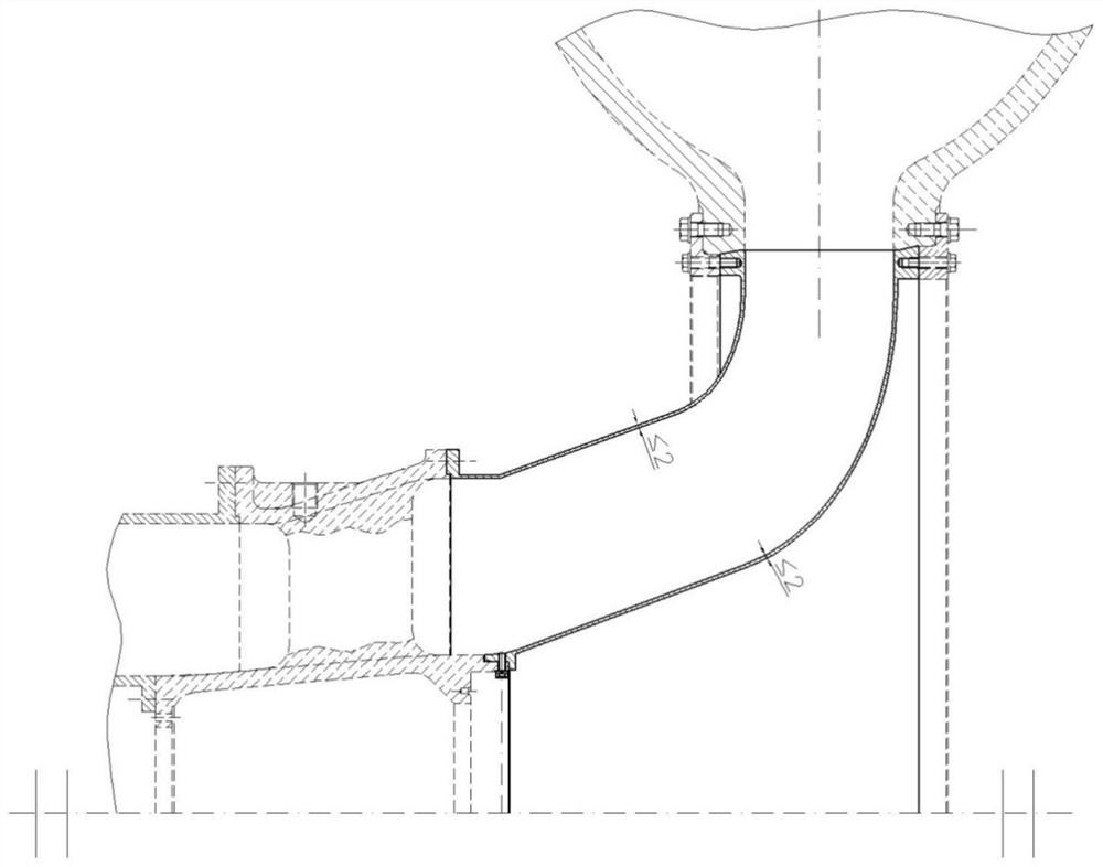
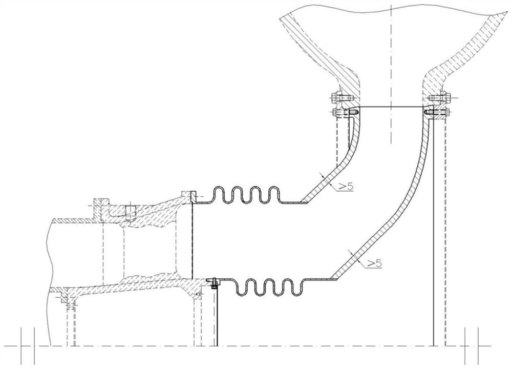
[0026] At present, the popular high-temperature and high-pressure steering parts on the market mainly adopt two methods: one is to use thin-walled steel plates with a wall thickness of no more than 2 mm to weld them, and use the deformation of the thin-walled parts to absorb the axial expansion of the test piece, such as figure 2 shown. The second is to use a thick-walled steel plate with a wall thickness of more than 5mm, and install an expansion joint at the front end of the steering section to absorb the axial expansion of the flow channel, such as image 3 shown.

[0027] figure 2 The main limitation of the structure shown is that due to the use of thin wall parts, the strength of the material limits its use conditions. According to practice, when the fluid pressure is higher than 350kPaA or lower than 20kPaA, the st...


PUM


Abstract

The invention belongs to the field of mechanical design, and particularly relates to an axial expansion self-compensating device for an annular runner steering part under high-temperature and high-pressure conditions. The axial expansion self-compensating device for the annular runner steering part under the high-temperature and high-pressure conditions comprises an inner steering shell section and an outer steering shell section, wherein the inner steering shell section and the outer steering shell section are both of an annular structure; one end of the inner steering shell section and one end of the outer steering shell section are connected with a connecting turbine test piece; and the other end of the inner steering shell section and the other end of the outer steering shell section are connected with an exhaust volute or an air inlet volute, wherein annular grooves are formed in the outer sides of the connecting positions of one ends of the inner steering shell section and the outer steering shell section and the connecting turbine test piece, annular sealing rings are arranged in the annular grooves, outer pressing rings are arranged on the outer sides of the inner steeringshell section and the outer steering shell section, the outer pressing rings are connected with the inner steering shell section and the outer steering shell section through bolts, and the inner steering shell section and the outer steering shell section are respectively connected with the turbine test piece in a sealing manner by extruding the sealing rings through the outer pressing rings. According to the axial expansion self-compensating device for the annular runner steering part under the high-temperature and high-pressure conditions, an expansion joint is not used, so that the axial length is shorter, and the application environment of the device is greatly widened.

Description

technical field [0001] The invention belongs to the field of mechanical design, and in particular relates to a self-compensating device for axial expansion of an annular flow path steering component under high temperature and high pressure conditions. Background technique [0002] In the application and test of aero-engines, gas turbines, flue gas turbines and related industries, sometimes it is necessary to divert the passage of high-temperature and high-pressure fluid. To ensure the safe operation of the channel under various working conditions. Contents of the invention [0003] Purpose of the invention: [0004] Provides an axial expansion self-compensating device for aero-engine turbine component testers, which solves the defects of limited application scenarios, low flexibility, and cumbersome installation and disassembly caused by the common structure of high-temperature and high-pressure steering components, and at the same time improves the service life and reduc...

Claims


Application Information

Patent Timeline
IPC IPC(8): F16L51/04G01M15/14G01M15/02
CPCF16L51/04G01M15/14G01M15/02
Inventor 刘志刚杨锐赵旺东娄术斌张晓东
Owner AECC SICHUAN GAS TURBINE RES INST
Why Eureka
Try Eureka