Multifunctional motor mounting rack

A mounting frame and multi-functional technology, which can be applied in the direction of machine/support, supporting machine, mechanical equipment, etc., can solve the problems of consuming workers' physical strength, easy to cause potential safety hazards, and increase workers' labor intensity, so as to improve the shock absorption effect and alleviate the Workers' labor intensity and the effect of less stress

Inactive Publication Date: 2021-03-19
SUSONG HUANRAN ELECTROMECHANICAL
View PDF10 Cites 1 Cited by
  • Summary
  • Abstract
  • Description
  • Claims
  • Application Information

AI Technical Summary

Problems solved by technology

[0002] During the production or maintenance of the motor, it is often necessary to move the motor to different positions. The movement of the existing small motors is often carried directly by hand. Manual handling is only suitable for short-distance movement, and long-distance movement will consume a lot of physical strength of workers. and prone to safety hazards
When moving long distances, the motor is often placed on a trolley. After the trolley moves the motor to the desired location, if the motor needs to be placed on the operating table, workers need to move the motor on the trolley to the On the operating table, the handling process of overcoming the gravity of the motor will also consume a lot of physical strength of the workers and increase the labor intensity of the workers

Method used


Image

  • Multifunctional motor mounting rack
  • Multifunctional motor mounting rack
  • Multifunctional motor mounting rack

Examples


Embodiment

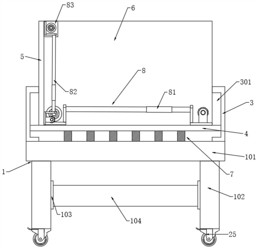
[0040] Please refer to the attached Figure 1-6 , a mounting frame for a multifunctional motor, comprising:

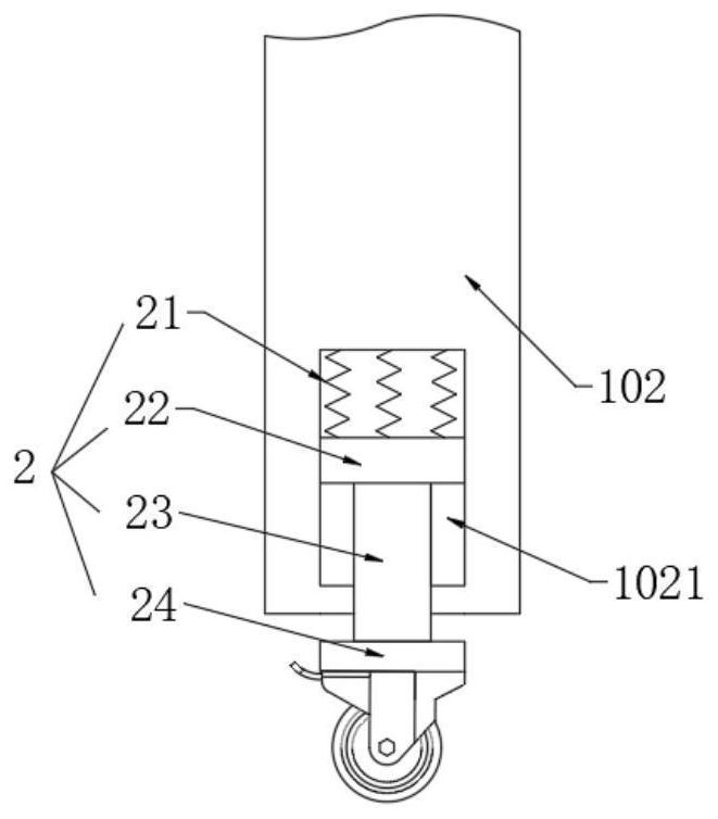
[0041] Support base 1, support base 1 comprises support plate 101, and the four corners of the support plate 101 lower surface are fixed with support legs 102 by screws, and the section of support leg 102 close to the ground is a cavity structure, and there are slides in the cavity. Groove 1021, the first damping device 2 is slidably connected to the chute 1021;

[0042] Further, in order to improve the shock absorption effect of the device when it moves, a section of the support leg 102 close to the ground is a cavity structure, and a chute 1021 is opened in the cavity, and the chute 1021 is slidably connected with the first shock absorption device 2 ;

[0043] A pair of skateboards 3, a pair of skateboards 3 are formed on the left and right sides of the support plate 101, and grooves 301 are formed on the adjacent surfaces of the pair of skateboards 3;

[0044]Fur...


PUM


Abstract

The invention discloses a multifunctional motor mounting rack. The multifunctional motor mounting rack comprises a supporting seat, a pair of sliding plates, a connecting plate, a second damping device and three groups of moving racks, wherein the supporting seat comprises a supporting plate, supporting legs are arranged on the lower surface of the supporting plate, the section, close to the ground, of each supporting leg is of a cavity structure, a sliding groove is formed in each cavity, and a first damping device is slidably connected to each sliding groove; grooves are formed in the surfaces, close to each other, of the pair of sliding plates; the connecting plate is formed between the pair of grooves in a sliding mode, a side plate is fixedly installed on one side of the connecting plate, and a back plate is fixedly connected between the connecting plate and the side plate; the second damping device is formed between the connecting plate and the supporting plate; and the three groups of moving racks comprise a first moving rack, a second moving rack and a third moving rack. The three groups of moving racks provide X-axis, Y-axis and Z-axis power output for movement of a motor,the problem that a large amount of manpower needs to be consumed due to the fact that the motor needs to be moved to different stations frequently during production or maintenance of the motor is solved, and the labor intensity of workers is relieved.

Description

technical field [0001] The invention belongs to the technical field of motor mounting frame equipment, and in particular relates to a mounting frame for a multifunctional motor. Background technique [0002] During the production or maintenance of the motor, it is often necessary to move the motor to different positions. The movement of the existing small motors is often carried directly by hand. Manual handling is only suitable for short-distance movement, and long-distance movement will consume a lot of physical strength of workers. And it is easy to have potential safety hazards. When moving long distances, the motor is often placed on a trolley. After the trolley moves the motor to the desired location, if the motor needs to be placed on the operating table, workers need to move the motor on the trolley to the On the operating table, the carrying process of overcoming the gravity of the motor to do work will also consume a large amount of physical strength of the worker...

Claims


Application Information

Patent Timeline
Patent Type & Authority Applications(China)
IPC IPC(8): F16M11/42F16M11/04F16M11/18F16F15/067
CPCF16M11/42F16M11/043F16M11/18F16F15/067
Inventor 吴勇何畅
Owner SUSONG HUANRAN ELECTROMECHANICAL
Why Eureka
Try Eureka