Burner cap and gas cooker applying burner cap

A burner and fire cover technology, applied in burners, gas fuel burners, applications, etc., can solve the problems of unfavorable stove combustion efficiency, high requirements on stove dampers, high airflow velocity, etc. The effect of better probability of fire transmission, better applicability and enhanced applicability

Active Publication Date: 2021-03-19
NINGBO FOTILE KITCHEN WARE CO LTD
View PDF13 Cites 0 Cited by
  • Summary
  • Abstract
  • Description
  • Claims
  • Application Information

AI Technical Summary

Problems solved by technology

[0004] The open fire transmission tank has the following defects: First, the open fire transmission tank is easy to cause blockage of the fire transmission tank, that is, the soup flowing down from the bottom of the pot is easy to flow into the fire transmission tank, and the blockage will affect the fire transmission performance. The main reason for the blockage and maintenance of the fire transmission channel; second, the open fire transmission channel has high requirements on the damper of the cooker, because after the damper is opened, too much air at one time will cause the air velocity to be too high, which will cause the flame to leave the flame or fall out during combustion. Therefore, the structural feature of the open fire transfer trough is poor flame stability. Therefore, to ensure the fire transfer performance of the open fire transfer trough, it is basically to close the damper very small, but the small damper is not conducive to the operation of the stove. The combustion efficiency is also not conducive to the emission of smoke, which greatly affects the performance of the stove
[0006] The fire transmission structure prevents the fire groove from being blocked by the fire transmission cover, but the setting of the fire transmission cover will also have an adverse effect on the entry of secondary air, and there is no flame stabilization structure in the fire transmission channel, and the flame stabilization effect is not good

Method used


Image

  • Burner cap and gas cooker applying burner cap
  • Burner cap and gas cooker applying burner cap
  • Burner cap and gas cooker applying burner cap

Examples


Embodiment 1

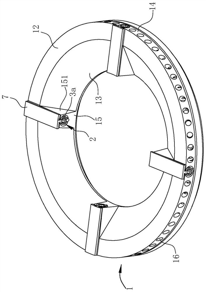
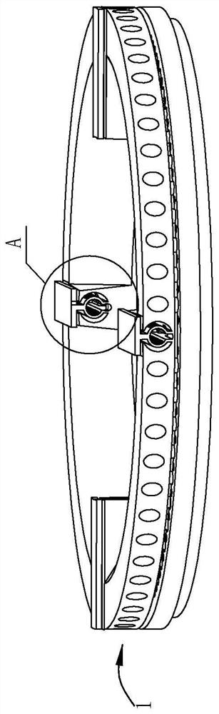
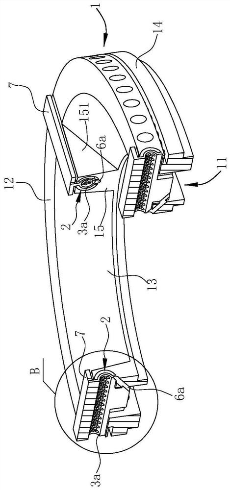
[0040] Such as Figure 1-7 As shown, the burner fire cover of this preferred embodiment includes a ring-shaped fire cover body 1, a fire transfer groove 2 located at the top of the fire cover body 1, a partition 3a located in the fire transfer groove 2, and a The cover plate 7 above the fire transfer tank 2. In this embodiment, there are four fire transfer grooves 2, which are radially distributed on the top of the fire cover body 1 along the center of the fire cover body 1, and each fire transfer groove 2 corresponds to a cover plate 7 and a partition 3a, hereinafter Take one of the fire transmission tanks 2 as an example. In this article, "inner" means close to the center of the fire cover body 1, and "outer" means away from the center of the fire cover body 1.

[0041] Such as Figure 1~4 As shown, the fire cover body 1 includes an annular top wall 12 and an inner ring wall 13 and an outer ring wall 14 extending vertically or obliquely downwards from the inner and outer ...

Embodiment 2

[0052] Such as Figure 8-14 As shown, the difference between Embodiment 2 and Embodiment 1 is that the structure of the partition 3b and the fire transfer groove 2 are different. The partition 3b of this embodiment is plate-shaped, and the longitudinal section of the fire transfer groove 2 is C-shaped.

[0053] In this embodiment, the partition 3b is in the shape of a vertical plate, and its upper end extends out of the fire transfer groove 2 to connect with the cover plate 7, so that the inside of the fire transfer groove 2 is divided into two areas by the partition 3b along its width direction, The two regions are respectively located on both sides of the partition 3b, and the through hole 31b penetrates through the wall thickness of the partition 3b. In this way, the two sides of the partition 3b are integrated and independent of each other, and the small hole (that is, the through hole 31b) stabilizes the flame, and the effect is the best, so that the fire transmission is ...

Embodiment 3

[0056] Embodiment 3 is a gas cooker using the fire cover of Embodiment 2:

[0057] Such as Figure 15 , 16 As shown, the cooker also includes a base 0 and an inner ring fire cover 8. The fire cover body 1 surrounds the outer side of the inner ring fire cover 8 and forms an annular channel 81 between the two, and an ignition needle 9 is arranged in the annular channel 81. There are two discharge electrodes 91 of the ignition needle 9, and the two discharge electrodes 91 point to the inner ring fire hole 82 and the fire transmission groove 2 of the inner ring fire cover 8 respectively, so even if one of the discharge electrodes 91 is polluted and cannot work, the other will also Can work for ignition.

[0058] The fire cap body 1 , the inner ring fire cap 8 and the ignition pin 9 are all arranged on the base 0 , which is a prior art, and will not be repeated here.


PUM


Abstract

The invention relates to a burner cap and a gas cooker applying the burner cap. The burner cap comprises an annular burner cap body, wherein a gas mixing cavity is formed in the bottom of the burner cap body; and a fire transferring groove penetrating in the radial direction of the burner cap body is formed in the top of the burner cap body, and is in fluid communication with the gas mixing cavity. The burner cap is characterized in that a separating piece is arranged in the fire transferring groove, extends in the length direction of the fire transferring groove and divides the interior of the fire transferring groove into two areas; a through hole is formed in the separating piece; and the two areas in the fire transferring groove are in fluid communication through the through hole in the separating piece. According to the burner cap and the gas cooker applying the burner cap provided by the invention, the interior of the fire transferring groove is divided into the two areas by theseparating piece, and the two areas are communicated with each other through the through hole, so that the two areas are integrated and independent of each other and can stabilize the flame, and the fire transfer is stable and reliable.

Description

technical field [0001] The invention belongs to the field of gas cookers, and in particular relates to a burner fire cover and a gas cooker using the same. Background technique [0002] At present, the fire transfer structure of burners on the market is mainly from the flame of the inner ring, which is transmitted to the fire hole of the outer ring through the fire transfer groove, so as to ignite the fire of the outer ring; during the transfer process, because the inner and outer rings are independent structures, it is necessary to set The fire transmission tank carries out fire transmission. [0003] The outer ring fire cover of the existing gas burner generally adopts an open fire transfer groove structure, such as the Chinese invention patent "a burner fire cover for a gas cooker" with the application number 201610930412.4 (publication number CN106642118A), patent No. The Chinese utility model patent of 200920202204.8 (authorized announcement number is CN201555225U) "a ...

Claims


Application Information

Patent Timeline
Patent Type & Authority Applications(China)
IPC IPC(8): F23D14/46F23D14/58F23D14/62F23D14/84F23D14/26F24C3/08F24C3/10
CPCF23D14/46F23D14/62F23D14/58F23D14/26F23D14/84F24C3/085F24C3/103
Inventor 吴丽波
Owner NINGBO FOTILE KITCHEN WARE CO LTD
Why Eureka
Try Eureka