
High-order attitude enhancement method based on angular rate input

A technology of angular rate and attitude, applied in the field of strapdown inertial navigation attitude calculation, can solve the problem of low navigation accuracy

Active Publication Date: 2021-03-19
SOUTHEAST UNIV
View PDF2 Cites 1 Cited by
  • Summary
  • Abstract
  • Description
  • Claims
  • Application Information

AI Technical Summary

Problems solved by technology

[0037] The purpose of the present invention is to solve the problem that the traditional angle rate input cone error compensation algorithm is limited by the number of samples in the attitude update period and ignores the influence of the tricross product term, which leads to the low navigation accuracy of the attitude algorithm in a high dynamic environment, and provides A high-order enhanced attitude method based on angular rate input, which can effectively reduce the cone error in the attitude algorithm without increasing the sampling frequency and attitude update frequency

Method used


Image

  • High-order attitude enhancement method based on angular rate input
  • High-order attitude enhancement method based on angular rate input
  • High-order attitude enhancement method based on angular rate input

Examples


Embodiment 1

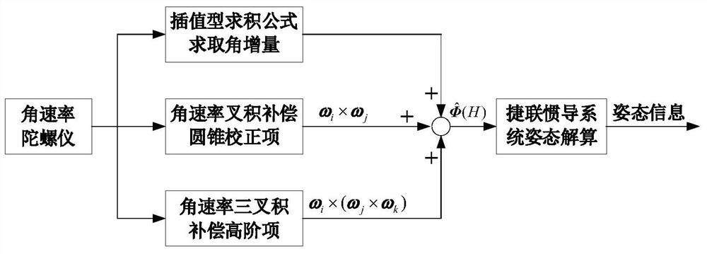
[0084] Such as figure 1 As shown, the present invention provides a high-order enhanced attitude algorithm based on angular rate input.

[0085] Specific steps are as follows:

[0086] First, the theoretical value of the rotation vector in one attitude update cycle is derived under typical coning motion;

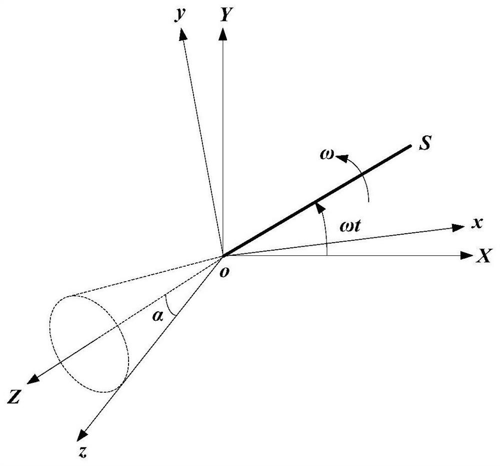
[0087] When the carrier performs a typical conical motion relative to the navigation coordinate system, the corresponding quaternion is shown in formula (19):

[0088]

[0089] Where ω is the angular frequency of the cone motion, and α is the half-cone angle of the cone motion. At this time, the projection of the carrier angular velocity vector ω(t) in the carrier coordinate system is:

[0090]

[0091] Then the z-axis theoretical value of the second-order rotation vector term δΦ cz (H) is:

[0092]

[0093] Z-axis theoretical value δΦ of the third-order rotation vector term Az and δΦ Bz They are:

[0094]

[0095] δΦ Bz =0 (25)

[0096] Due to δΦ Bz is...

Embodiment 2

[0137] In this embodiment, it is assumed that the gyroscope performs 2 samplings in one attitude update cycle (such as figure 2 shown), the specific steps are:

[0138] Step 1. In an attitude update cycle, sample the output of the gyroscope twice to obtain the angular velocity of the carrier motion ω 1 , ω 2 , and extract and store the angular rate ω in the last attitude update period in the computer -2 , ω -1 , ω 0 .

[0139] Step 2. Use the Lagrangian interpolation integration method to integrate the 5 angular rates, then the estimated value of the gyroscope angle increment in one attitude update cycle for:

[0140]

[0141] Step 3. Using the angular rate information in the previous attitude update period and the current attitude update period, calculate the estimated value of the second-order rotation vector term in the current attitude update period

[0142]

[0143] Step 4. Using the angular rate information in the previous attitude update period and the ...


PUM


Abstract

The invention discloses a high-order attitude enhancement method based on angular rate input, and belongs to the field of strapdown inertial navigation. According to the method, angular rates in a previous attitude updating period and a current attitude updating period are utilized, firstly, Lagrange interpolation is carried out on the angular rates, integration is carried out in the current attitude updating period to estimate angular increment, and then a linear combination of angular rate binary products is utilized to estimate a second-order rotation vector term in a non-exchangeable error, and then, a third-order rotation vector item in the non-exchangeable error is estimated by utilizing a linear combination of angular rate ternary products, and finally a rotation vector in an attitude updating period with the obtained approximate values of the angular increment, the second-order rotation vector item and the third-order rotation vector item, so that the non-exchangeable error caused by rigid body rotation is effectively reduced; and the attitude calculation precision is further improved.

Description

technical field [0001] The invention relates to a high-order enhanced attitude method based on angular rate input, and belongs to the technical field of strapdown inertial navigation attitude calculation. Background technique [0002] In the strapdown inertial navigation system (Strapdown Inertial Navigation System, SINS), the gyroscope is directly fixed to the carrier, and is sensitive to the angular motion of the carrier relative to the inertial space. The performance of attitude algorithm directly affects the navigation accuracy of SINS. Due to the non-exchangeability of finite rotation, coning error is inevitably introduced into attitude calculation, especially in high dynamic environments. Savage believes that it is reasonable for the error of the navigation algorithm to be less than 5% of the error caused by the inertial device, so with the continuous development of the inertial device, the accuracy of the navigation algorithm also needs to be improved, so it is necess...

Claims


Application Information

Patent Timeline
IPC IPC(8): G01C21/16G01C25/00G06F17/13G06F17/16
CPCG01C21/16G01C25/005G06F17/13G06F17/16
Inventor 程向红丁鹏王依能
Owner SOUTHEAST UNIV
Learn More