
Method for reducing OPC model residual error

A residual error and model technology, applied in the field of reducing the residual error of the OPC model, can solve the problem of low precision of the OPC model, achieve the effect of improving the correction efficiency, reducing the residual error of the model, and improving the accuracy

Inactive Publication Date: 2010-12-22
SEMICON MFG INT (SHANGHAI) CORP
View PDF5 Cites 0 Cited by
  • Summary
  • Abstract
  • Description
  • Claims
  • Application Information

AI Technical Summary

Problems solved by technology

[0005] The purpose of the present invention is to provide a method for reducing the residual error of the OPC model to solve the problem of low precision of the OPC model caused by the large residual error of the model

Method used


Image

  • Method for reducing OPC model residual error
  • Method for reducing OPC model residual error
  • Method for reducing OPC model residual error

Examples


Embodiment Construction

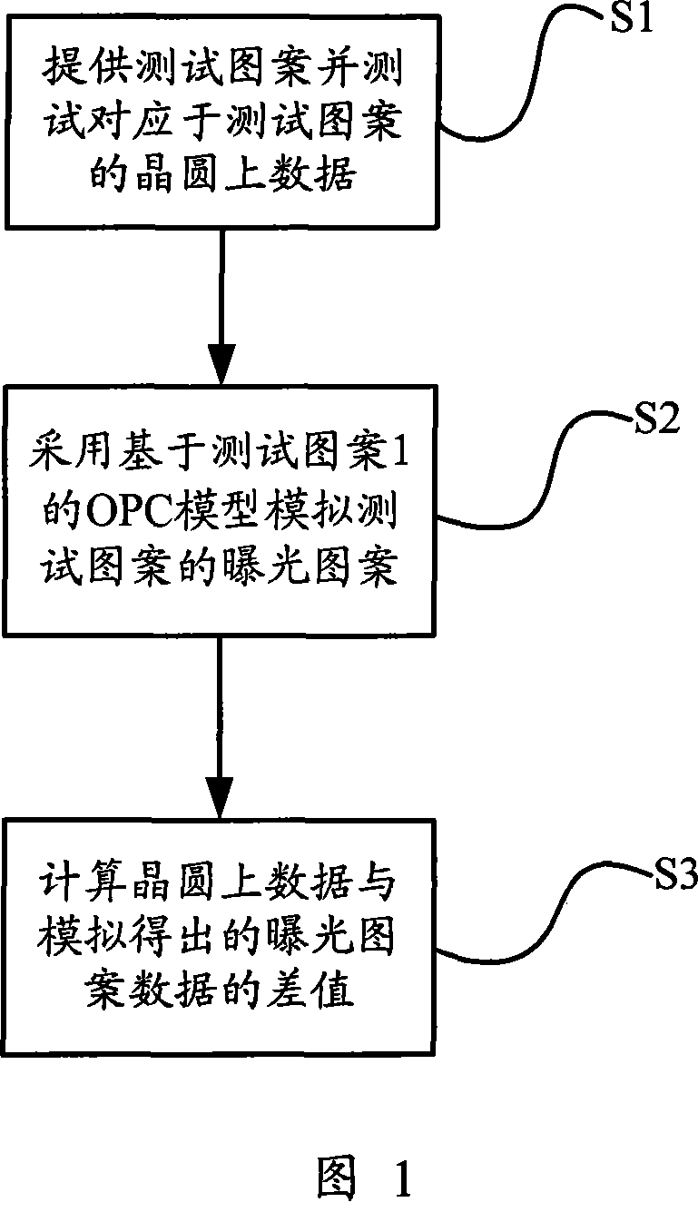
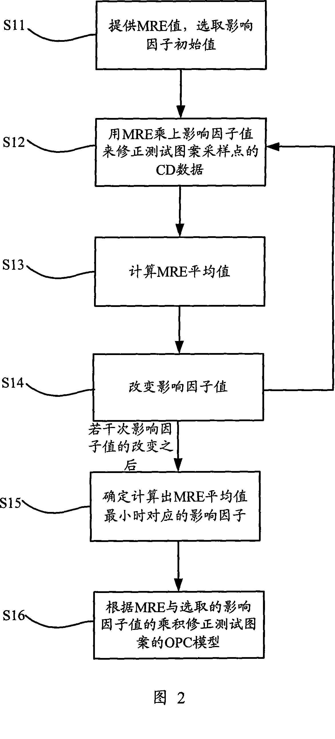
[0014] For the schematic diagram of the method of obtaining the residual error of the OPC model, please refer to figure 1 . It has been described in detail above, so it will not be repeated here. For the method of reducing the residual error of the OPC model of the present invention, please refer to figure 2 . It consists of six steps in total. Step S11 , providing model residual error values ​​for a series of sampling points on the test pattern, and selecting an initial value of the influencing factor. The model residual error values ​​for a series of sampling points on the test pattern can be obtained by figure 1 obtained by the method shown. In step S12, the CD data of the sampling points on the test pattern is corrected after multiplying the model residual error values ​​of all the sampling points on the test pattern by the value of the impact factor. However, the value of the influence factor multiplied by the model residual error of all sampling points of the test...


PUM


Abstract

The present invention provides a method for reducing OPC model residual error, the method comprises: multiplying the obtained OPC model residual error and the CD data of selected influencing factor value correction OPC model simulation pattern; then calculating the average value of the correction model residual error and calculating the average value of the OPC model residual error obtained underdifferent influence factors by changing the influence factor values; integrative comparing the average values of the model residual errors calculated by different influence factors to determine the corresponding influence factor value when the model residual error average value is minimum; multiplying the influence factor and the residual error value of design pattern sampling point simulated by the OPC model to correct the CD data of design pattern sampling point simulated by the OPC model, thereby effectively reducing the OPC model residual error, improving the accuracy of the OPC model andimproving the OPE correcting efficiency.

Description

technical field [0001] The invention relates to the field of optical proximity correction (OPC), in particular to a method for reducing the residual error of an OPC model applied to OPC. Background technique [0002] With the higher integration of integrated circuits, its manufacturing technology is constantly developing towards smaller feature sizes. However, the photolithography process has become the main bottleneck restricting the development of integrated circuits to smaller feature sizes. The main principle of the photolithography process is to project the design layout of the integrated circuit on the mask onto the wafer through a light source. However, as the feature size decreases, the optical distortion and abnormal shape of the projected image on the wafer make it difficult for the feature size (Critical Dimension: CD) of the projected small feature size pattern to meet the expected requirements, thus affecting the entire optical system. The yield rate of the en...

Claims


Application Information

Patent Timeline
Patent Type & Authority Patents(China)
IPC IPC(8): G03F1/36G03F1/14
Inventor 张飞王伟斌
Owner SEMICON MFG INT (SHANGHAI) CORP
Learn More