Monitoring device and method for monitoring and early warning of hydraulic structure

A technology for hydraulic structures and monitoring devices, which is applied to measurement devices, instruments, etc., can solve the problems of low monitoring range and adaptability, and inability to verify monitoring results from other angles.

Active Publication Date: 2021-03-19
中国水利水电勘测设计协会
View PDF10 Cites 0 Cited by
  • Summary
  • Abstract
  • Description
  • Claims
  • Application Information

AI Technical Summary

Problems solved by technology

[0003] Commonly used monitoring items mainly include deformation monitoring, seepage monitoring, stress and strain monitoring, leakage monitoring, seismic monitoring, hidden danger monitoring, temperature monitoring, etc. Patent CN205038019U discloses a dam anti-leakage monitoring device, including a dam body and a monitoring system. An anti-seepage slope is arranged on the dam body; the key points of the structure are: an anti-corrosion layer is arranged on the surface of the anti-seepage slope, a concrete fixed layer is arranged on the lower part of the anti-corrosion layer, and a waterproof coiled material layer is arranged on the lower part of the concrete fixed layer , the lower end of the dam body is provided with an anti-seepage body; the monitoring system is connected with a detector through a signal line, and the detector is connected with a probe group, and the probe group is completely inserted into the anti-seepage slope on the dam body, It has the advantages of good anti-interference, stable performance, and accurate detection results, but the monitoring range and adaptability are not high, and the monitoring results cannot be verified from other angles, which is not conducive to identifying the cause of hidden dangers

Method used


Image

  • Monitoring device and method for monitoring and early warning of hydraulic structure
  • Monitoring device and method for monitoring and early warning of hydraulic structure
  • Monitoring device and method for monitoring and early warning of hydraulic structure

Examples


Embodiment 1

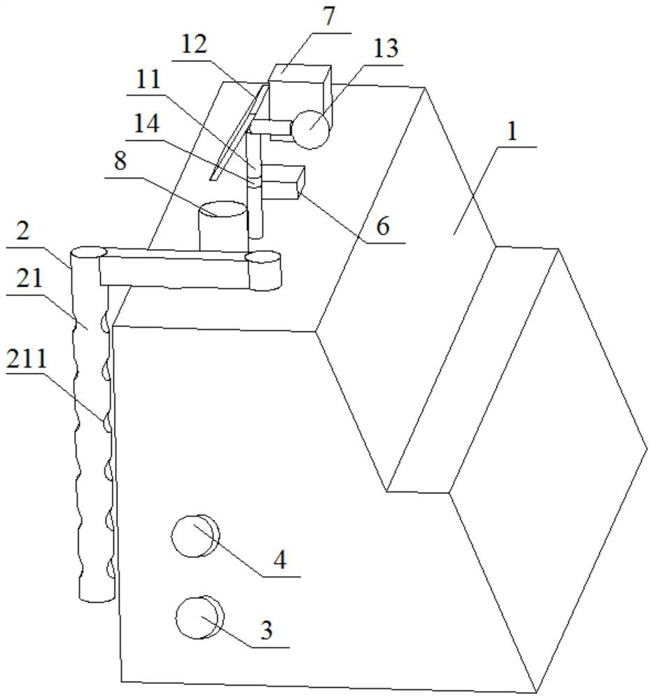
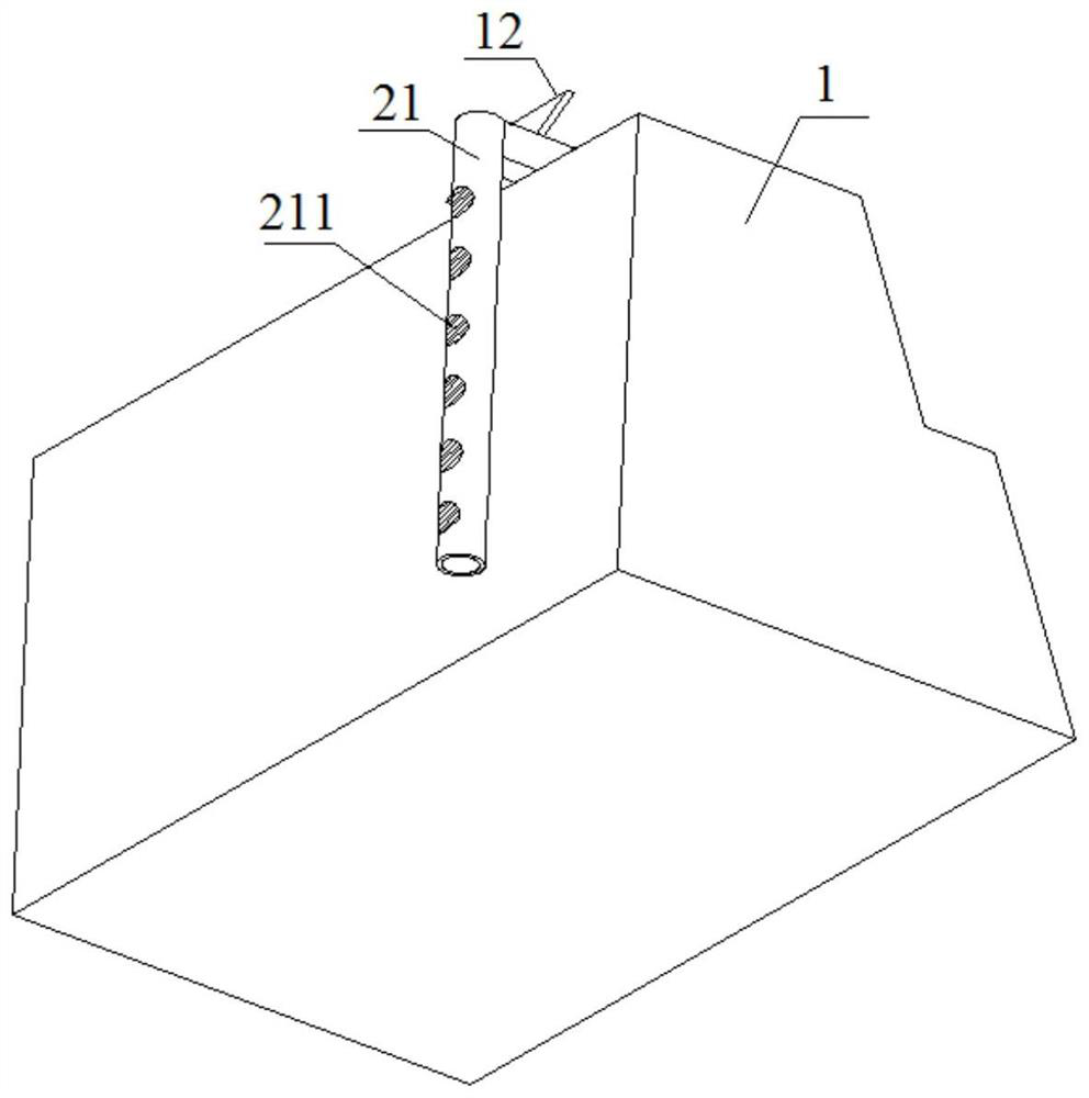
[0038] Such as figure 1 As shown, a hydraulic structure monitoring and early warning monitoring device, the hydraulic structure is a dam used for water retention or water delivery, specifically a concrete dam or an earth dam, including a hydraulic structure body 1, The upper surface of the main body 1 is provided with a pole 11, and one side of the upper end of the pole 11 is provided with a solar panel 12 for providing electric energy for each monitoring part. The solar panel 12 is a commercially available solar panel, and the other side of the upper end of the pole 11 is provided with a camera 13. The camera 13 is a commercially available AK-NH9000s high-definition camera. The pole 11 below the camera 13 is provided with an audible and visual alarm 14. The audible and visual alarm 14 is a commercially available TGSG-01T audible and visual alarm. The audible and visual alarm 14 The controller is connected to the sensors of each monitoring section.

[0039] Such as figure 2...

Embodiment 2

[0049] The present embodiment is basically the same as Embodiment 1, the difference lies in the monitoring of rainfall:

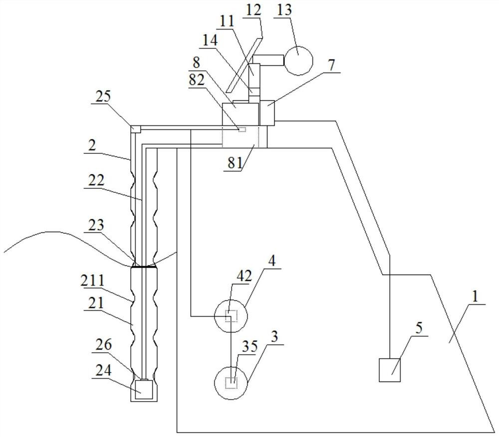
[0050] Step 4 also includes: when the rainfall monitored by the rainfall monitoring unit 8 is greater than 30 mm, the rainfall sensor 82 transmits a signal to the pressure sensor 42, so that the pressure sensor 42 reduces the value of the alarm signal triggered by the piezometer 41 from 1 MPa to 0.7 MPa At the same time, the rainfall sensor 82 transmits the signal to the temperature and humidity sensor 35, and the temperature and humidity sensor 35 transmits the signal to the controller 36, and the controller 36 controls the motor 32 to drive the temperature and humidity meter 33 to reciprocate along the transmission rod 34 to perform dynamic monitoring of temperature and humidity , Strengthen the temperature and humidity monitoring of various parts inside the hydraulic structure body.

Embodiment 3

[0052] This embodiment is basically the same as Embodiment 2, except that the positions of the temperature and humidity monitoring part 3 and the osmotic pressure monitoring part 4 are adjusted according to the length and height of the body 1:

[0053] Step 1: The main body 1 of the hydraulic structure is 23.8m long and 3.4mm high, and the water level monitoring part 2 is arranged on the upstream side of the main body 1, and the drill bit is used to drill a hole 72cm from the bottom on the main body 1 side and arrange the temperature and humidity Monitoring section 3, lay out osmotic pressure monitoring section 4 at 40 cm above the temperature and humidity monitoring section 3, lower the temperature and humidity meter 33 into the temperature and humidity monitoring section 3, and arrange osmotic pressure gauges 41 on the osmotic pressure monitoring section with a group interval of 50 cm. In the part 4, the stress and strain monitoring part 5, the surface displacement monitoring...


PUM


Abstract

The invention discloses a monitoring device and method for monitoring and early warning of a hydraulic structure. The device comprises a body of the hydraulic structure, a water level monitoring partlocated at one side of the body, a temperature and humidity monitoring part which is located in the body, is 60 to 80cm away from the bottom, and is transversely parallel to the surface of the body, and a seepage pressure monitoring part which is located 30 to 50cm above the temperature and humidity monitoring part, transversely parallel to the surface of the body, and arranged in the body. Each monitoring part is connected with a signal acquisition box, and an audible and visual alarm is further arranged above the body. According to the invention, the hydraulic structure can be monitored for24 hours, various indexes such as the water level, the internal temperature and humidity, the osmotic pressure, the displacement and the stress strain of the hydraulic structure are monitored in realtime, monitored data are uploaded, it is ensured that the hydraulic structure is in a safe state for a long time, and certain economic benefits are achieved.

Description

technical field [0001] The invention relates to the technical field of monitoring hydraulic structures, in particular to a monitoring device and a monitoring method for monitoring and early warning of hydraulic structures. Background technique [0002] Hydraulic structures include various dams, sluices and dikes, etc. Since the working conditions of hydraulic structures are very complicated, once an abnormal state is found during long-term operation, it must be found and dealt with in time, otherwise it will lead to serious consequences. Safety monitoring is the most important work in hydraulic engineering management. Its purpose is to analyze and evaluate the safety degree of hydraulic structures, so as to take timely measures to ensure the safe operation of hydraulic structures. At present, the safety monitoring system of hydraulic structures has realized semi-automation or automation, and observes and measures the operating status and changes of the buildings through inst...

Claims


Application Information

Patent Timeline
Patent Type & Authority Applications(China)
IPC IPC(8): G01D21/02
CPCG01D21/02
Inventor 计炳生李浩宋扬王萌茜
Owner 中国水利水电勘测设计协会
Why Eureka
Try Eureka